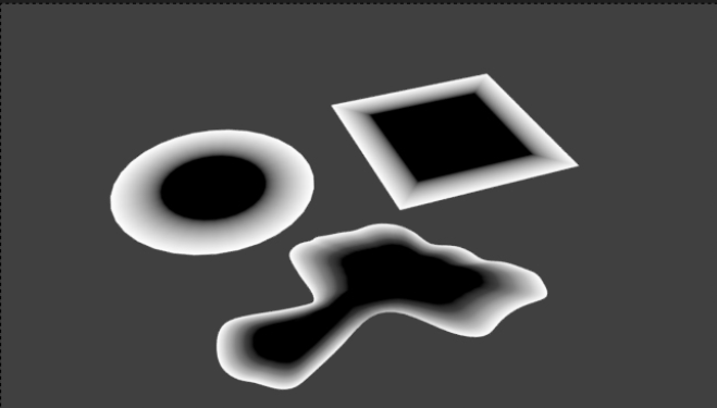
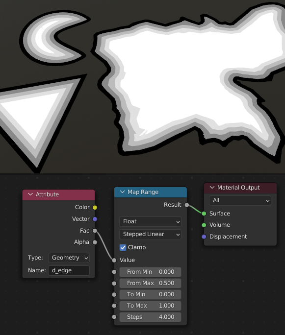
My aim is to create a border around a dynamically changing flat surface. AO and Pointiness don't work obviously. The image below is from here which illustrates my goal somewhat. I would like to have two stripes that follow the contour of the edge. I'm trying to do this in the shader editor although GeoNode suggestions are welcome. I'm sure there is some mathematical solution but it is out of my scope to work out. Thank you in advance.
4 Answers
Here's an in-shader technique that will work only for Cycles:
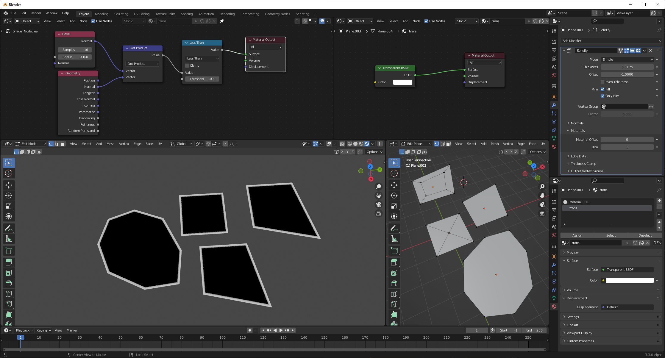
Shown with multiple topologies to demonstrate generalizability.
We have (flat-shaded), planar meshes. We use a solidify modifier to create a rim for these meshes, and then assign that rim a material offset to a transparent material so it won't be drawn. This allows the bevel node to work on the edges, smoothing out their normals; we can compare the beveled normal to the base normal and look for any differences. The size of the edge line is provided in object space units, in the radius provided to the bevel node.
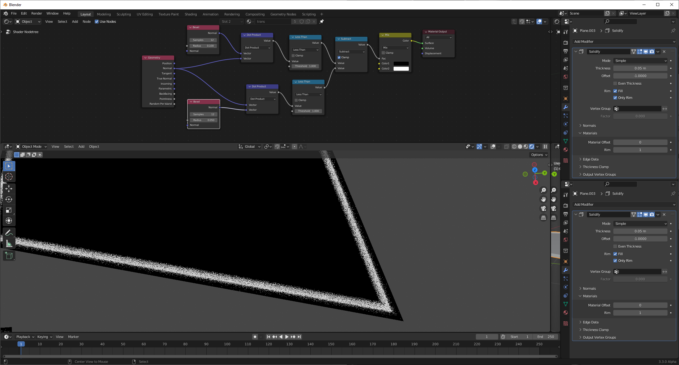
If we'd like, we can combine multiple bevel nodes, with varying radii, to create arbitrary shapes for our outline:
Bevel nodes only work in Cycles, and are inherently noisy, relying on multiple sampling. The advantage to this technique is that it doesn't vary with mesh topology/vertex density; the thickness is easily controllable.
-
$\begingroup$ Nice use of Solidify features. Clever :) $\endgroup$– Robin Betts ♦Commented Jun 22, 2022 at 20:16
This is just a tweak of @Chris ' answer, really..
A limitation of these GN approaches is that information is stored on the geometry. In the spaces between the stored values on points or face-corners, values must be interpolated. This makes the resolution dependent on mesh density, and/or the quality dependent on the mesh topology.
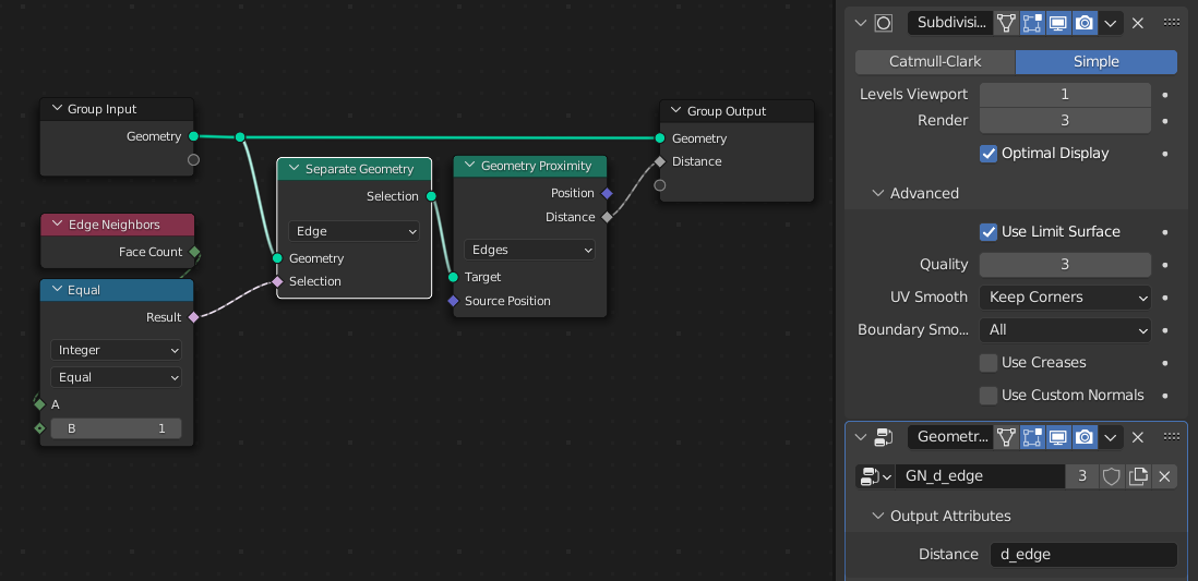
Since the effect varies from shape to shape, it may be worth simplifying the distance-to edge storage as much as possible, and handing over some responsibility to a Subdivision Surface modifier above it, which can bump up the resolution only at render time:
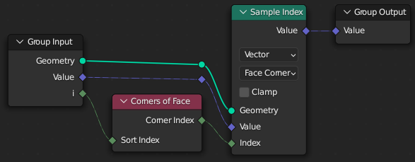
Your GN Output Attribute can be used in a shader in some way like this:
-
$\begingroup$ Makes me wonder… What if for each face multiple attributes were stored, storing each vertex position and distance to edge, to allow for the shader to make a custom interpolation 🤔 Something like a signed distance field font rendering perhaps… $\endgroup$ Commented Dec 9, 2022 at 14:25
-
$\begingroup$ @MarkusvonBroady easier to store d2edge on reasonably dense vertices internal to the region? The shader could still map the linear interpolation to something else... Not sure how you would store 1-to-unknown-many on faces, at the moment? $\endgroup$– Robin Betts ♦Commented Dec 9, 2022 at 16:39
-
$\begingroup$ I would just assume at most n vertices, maybe 6? Or triangulate. $\endgroup$ Commented Dec 9, 2022 at 19:00
-
$\begingroup$ @MarkusvonBroady Ahh! OK, a hack .... :P ... just teasing.. but still, that seems to me to be fighting the system.. GN asks us to do that rather a lot, atm. $\endgroup$– Robin Betts ♦Commented Dec 9, 2022 at 19:05
-
$\begingroup$ In this case the problem of this solution would translate to other programming environments, as in general shaders don't have access to such data as getting distance to some geometry. So I don't know if it's fighting the system, I don't know how Blender could be improved to allow a shader to calculate a distance to edge easily. 🤔 $\endgroup$ Commented Dec 9, 2022 at 20:57
well...there is a "kind of" workaround, if you are willing to use some more modifiers ;)
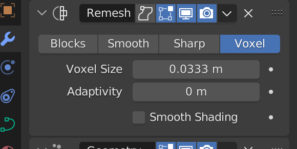
so first modifier, Remesh, so we will have Quads as faces.
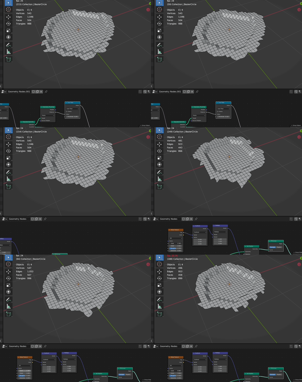
second modifier: GN with this node setup:
i just set the z position here to show you the edge detected...of course you could do whatever you want with that information...
Play around with "Remesh voxel size", "less than" value and "merge by distance value" to get the accurate result you want to have.
Using the distance of geometry proximity you can create easily gradient as in your images provided.
video tutorial: https://youtu.be/UyBi2F3J7Oc
-
1$\begingroup$ Amazing thank you. This answered a completely different problem I had which was converting my Geo Nodes to quads. Many thanks. $\endgroup$– AlanCommented Jun 22, 2022 at 6:31
-
This is just a tweak of @Robin Betts ' answer, really..
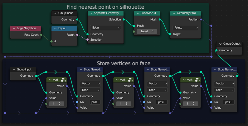
When storing data on points, a shader will interpolate the Attribute value by averaging between the triangle vertices, giving the values from those vertices weight depending on the distance to them, which creates gradients. Problem is, when displaying the distance to plane silhouette, you don't want to display an average distance of face corners, you want to display the minimum distance. So what I'm doing is:
- Triangulate.
- For each face store each vertices calculated data.
- The calculated data is the position of the nearest point on the silhouette.
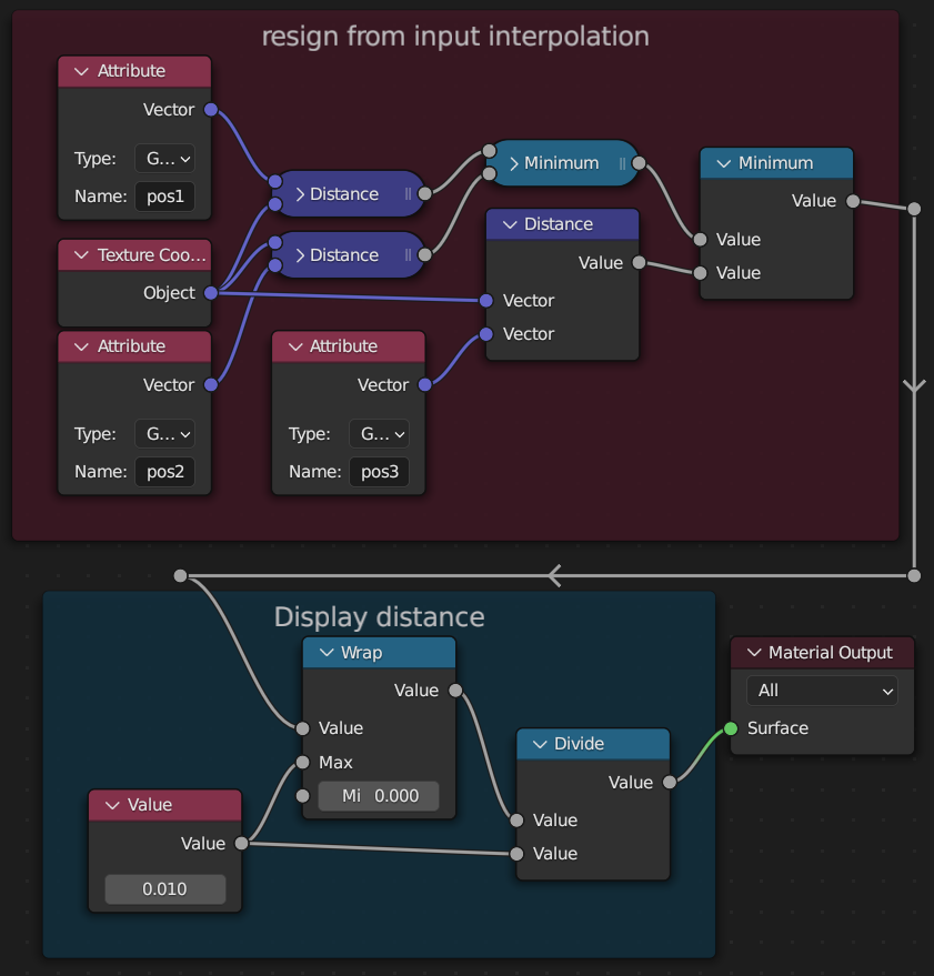
In the shader, calculate the distances from currently evaluated point to each of the 3 stored positions.
Obtain the minimum out of those 3 distances, and display it.
3 samples are not necessarily enough and I can imagine someone e.g. also store positions closest to the edges of the triangle, or just an arbitrary number of positions in a circle around the center of the face. However, it seems in practice those 3 samples are enough, as you can see on the test below:
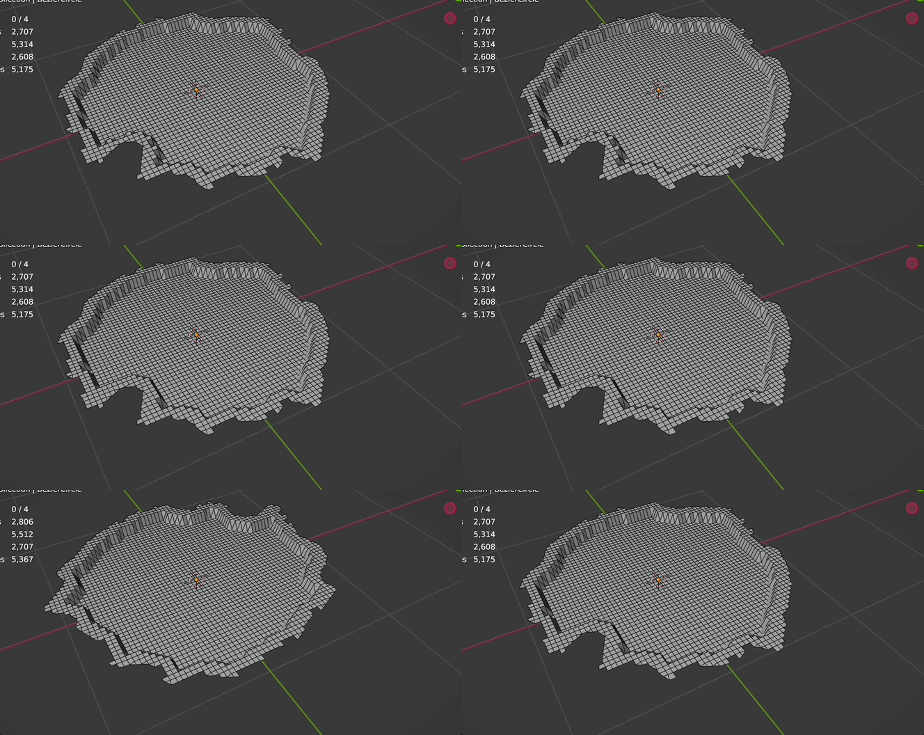
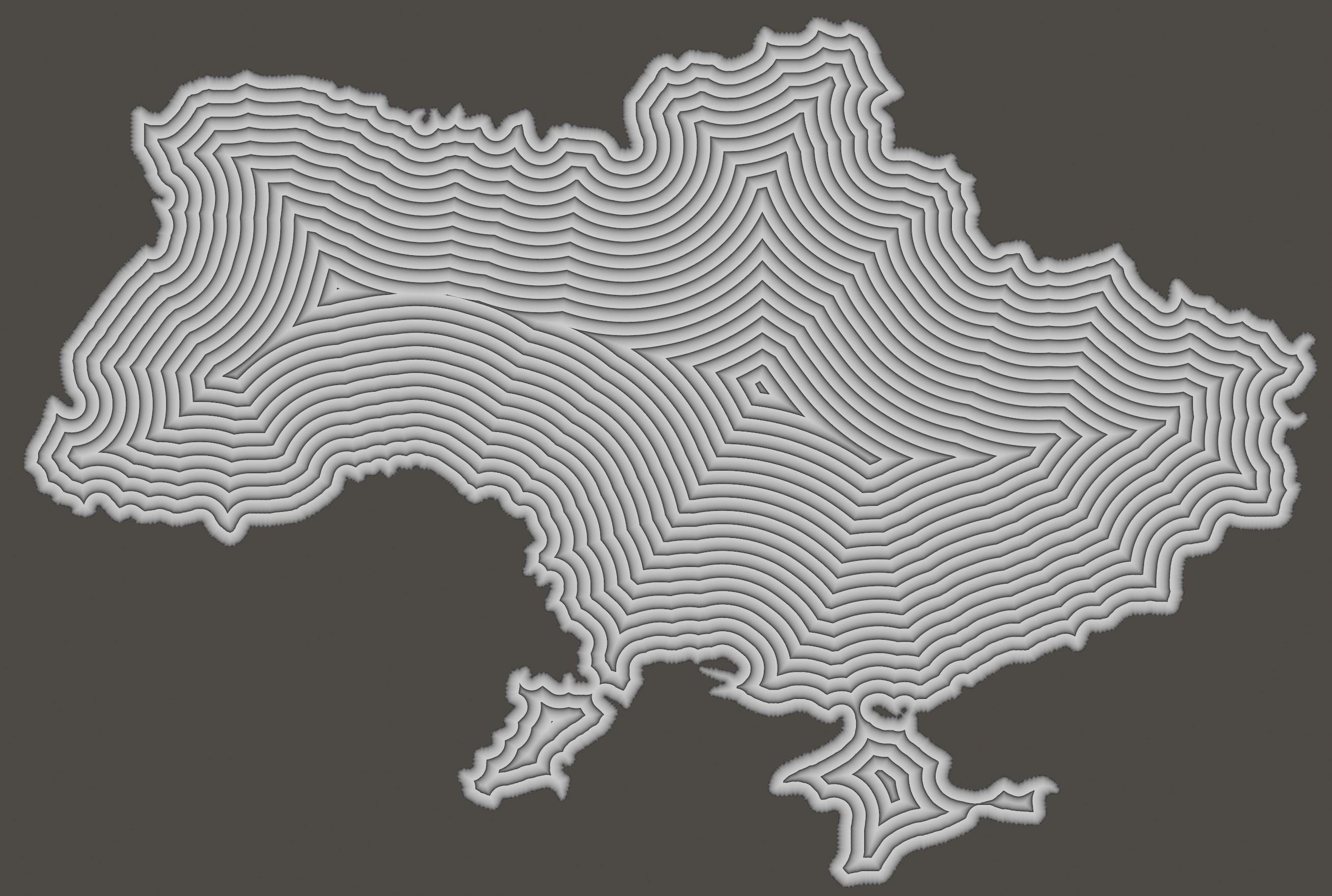
Robin Betts' solution:
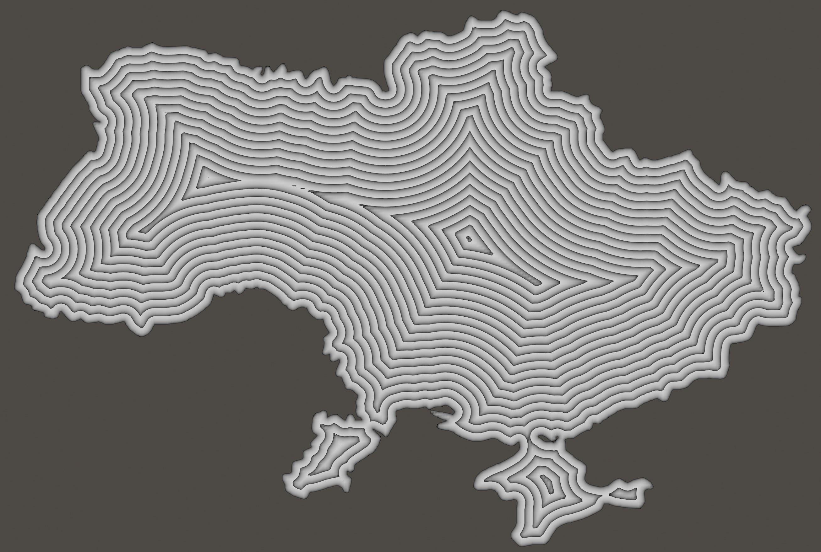
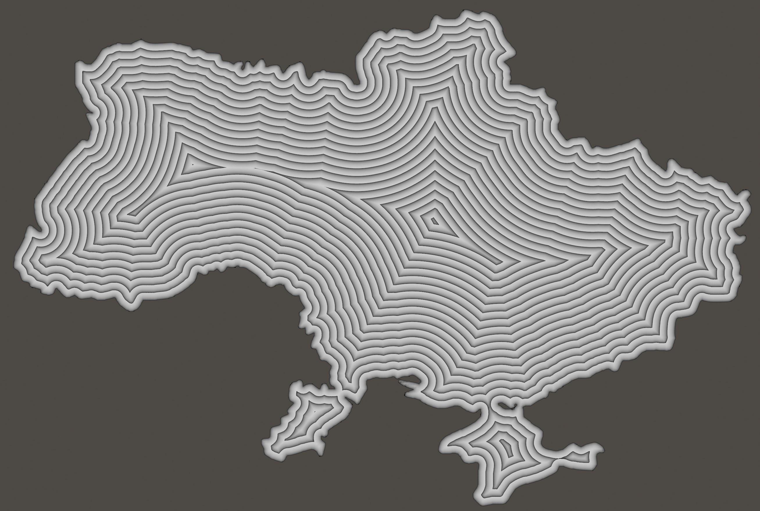
My tweak:
Whoops! My solution breaks the effect near the silhouette. What we actually want is this:
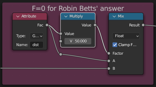
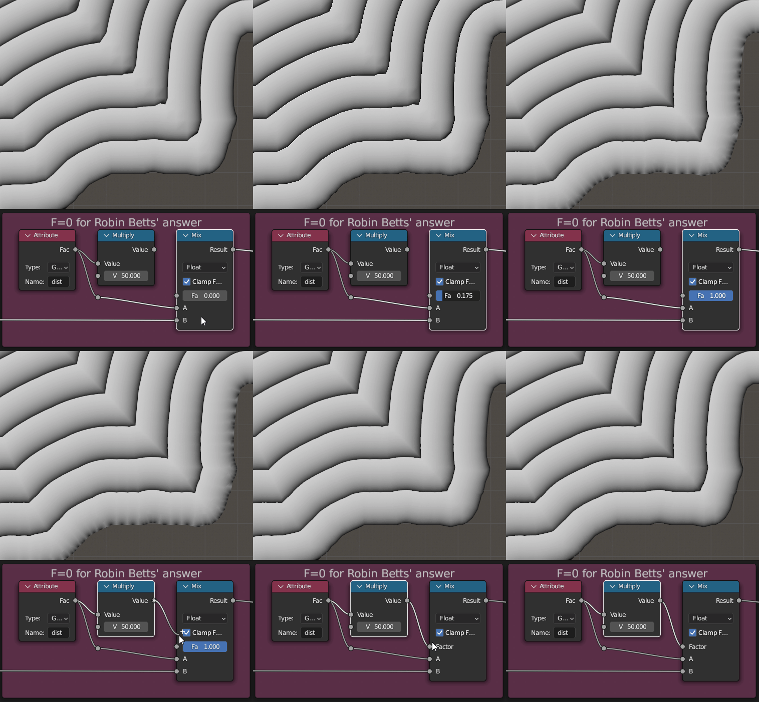
Which I achieved by ad hoc patching using an interpolation between the two solutions:
Here's an animated comparison:
-
1$\begingroup$ Hehe.. only just spotted this one ..:) $\endgroup$– Robin Betts ♦Commented Oct 8, 2023 at 20:29

