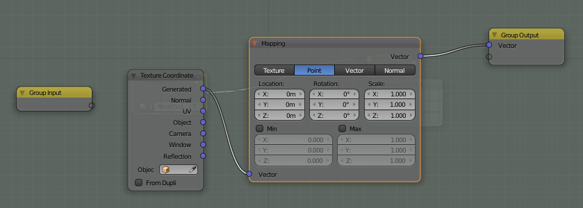
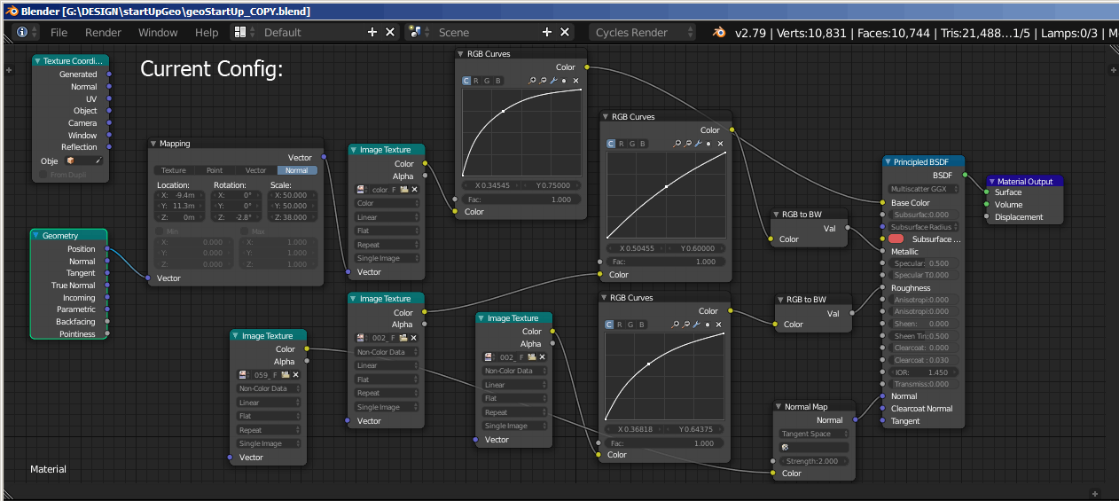
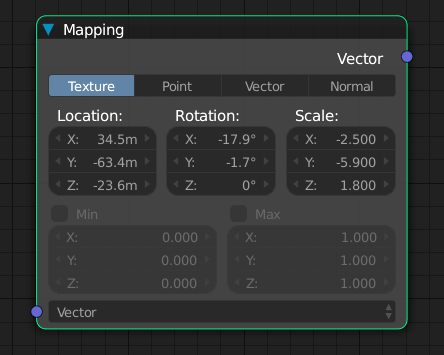
I'm using a node group which has vector mapping in it. Unfortunately, there is no socket to connect the scale/rotation/location to either the node group input, or another node. Any ideas on how this could be accomplished?
3 Answers
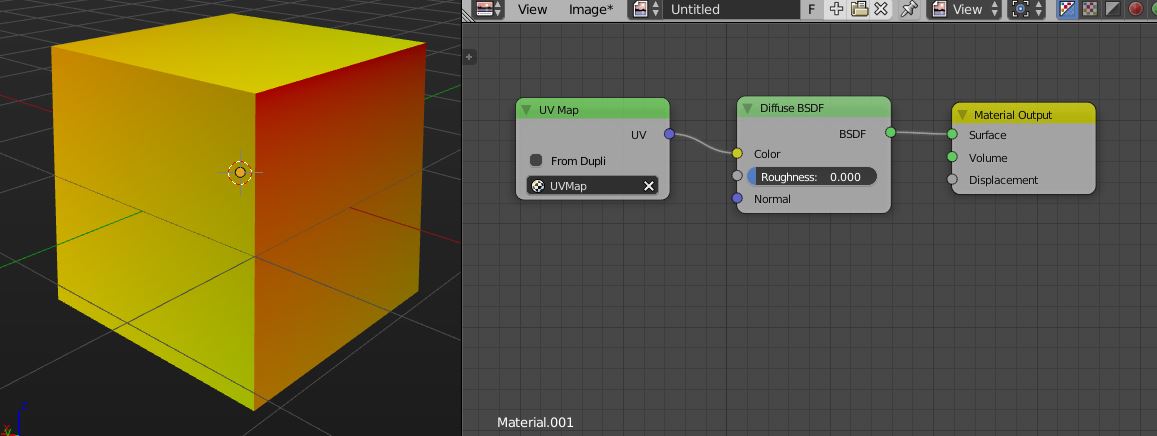
You can create your own node groups to do that. First, let's start with examining what UVs are, or better how you can think of them. Start with creating a cube and unwrap it. Note that in the latest Blender version, you can even choose to automatically create texture coordinates from the last operator panel. Then create a node setup like in the screenshot here:
Note that you should connect the UV output of the Map Node into the Color of a Shader. This way, you can see what a UV Map 'looks like'. UVs are 2D coordinates of vertices / faces of your mesh. They exist in a space which ranges from 0 to 1. The 3D vector you get from the UV Map node carries the U direction in the first slot, the V direction in the second, and 0 in the third. check these screenshots:
you'll see that the map, if you split it out into its U and V sub components, gives you a gradient. Black is equal to 0, and means (for the U direction) left hand side in the UV Image editor, and in the end also in the texture which you map. For the V direction it means bottom, while white (= 1) means top.
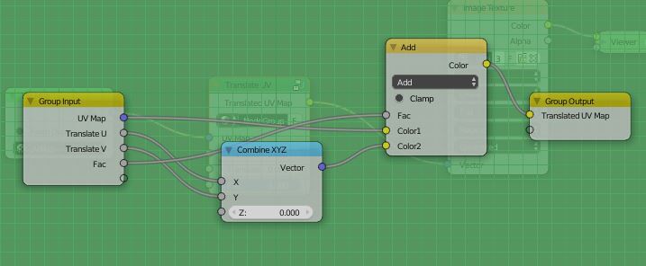
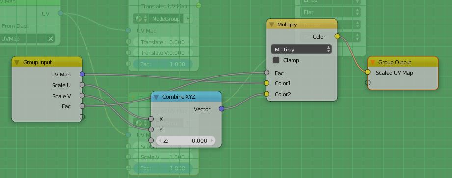
So how to bring this in connection with the operations Translate, Rotate and Scale? Let's handle them one by one, starting with Translation. Since 0 means left / bottom, and 1 means right / top, one can simply add arbitrary values to move the UVs across the texture. Yes, you move the UVs, not the texture, which mathematically is something different. It will nonetheless enable you to do what you want. To do it, you can use any node which allows you to manipulate three channel input. You can use the SplitXYZ node and the Vector Transform node, but you can also use the MixRGB Node. In this case, it is the easier choice, because it has one additional element: the Fac socket:
In this example, I used the CombineXYZ node as the input node. It has one advantage over a simple RGB color node: You can set negative values. As you can see, you only need two of the sockets. Now, let's fool around with the Fac input:
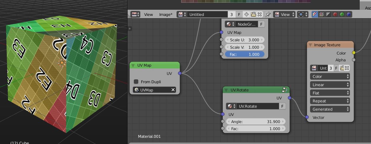
To go further, let's create a node group so we can reuse what we have in other Blend files. Publish the socket values like in the screenshot, so you can add Noise or other effects to your result:
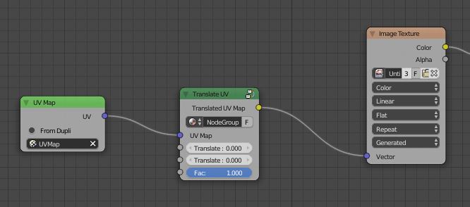
And this is what the result looks like from the outside:
Give it a nice name, add a fake user, and consider even to save this in your startup file to have it around every time you create a new file. Now let's handle Scaling. Luckily, this is really easy, because the logic is exactly the same as for rotations. The only change here is the math operation inside the node group: Make a duplicate of the node group, and change the math operation of the MixRGB Node from ADD to MULTIPLY, that's it:
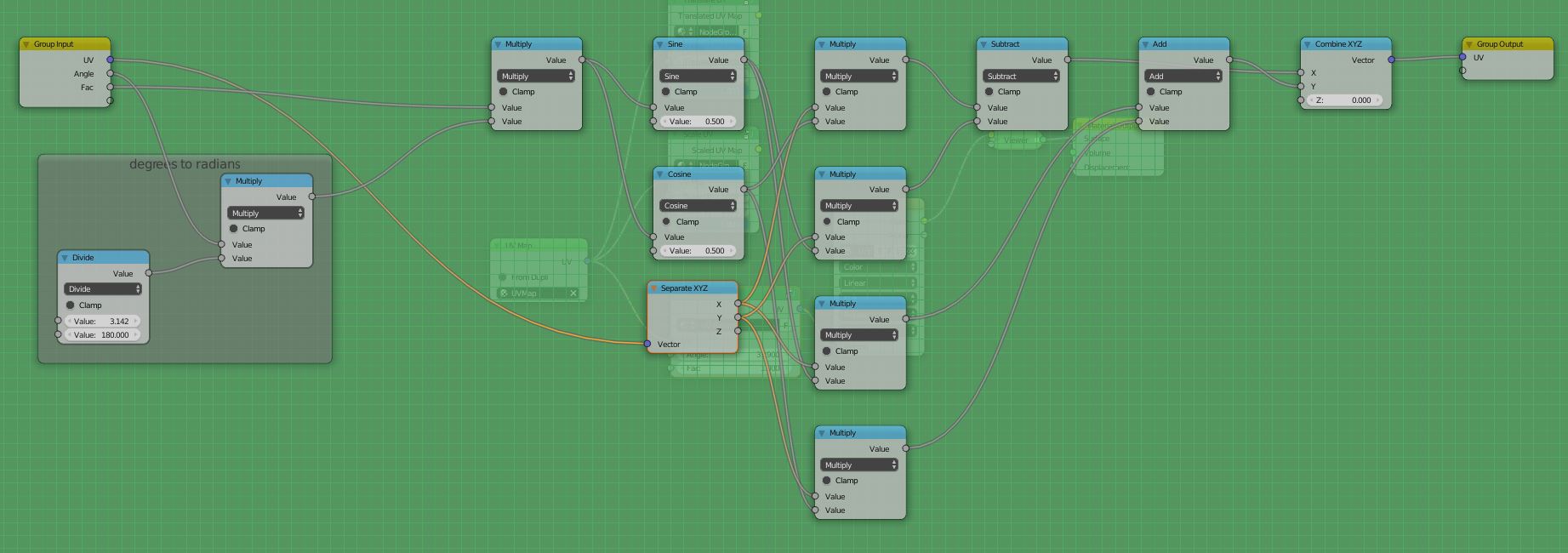
Rotations are the ones that makes peoples minds crack. I admit that I didn't come up with the following node tree entirely myself, I took it from online references. Search for "rotate 2D vector" or "rotate 2D coordinates" to find the math equation, and build it with nodes like this:
The first multiply node basically gives you the Fac value for the Node group again. It was a deliberate decision to put it here like this, you can create variations of it if you like. The framed part is a conversion setup, because for the Node Group, the user most likely wants to type in rotations as Degrees, but Blender handles rotations in radians. That few nodes handle the conversion (pi / 180 * rotationvalue). The rest is trigonometry functions to rotate the coordinate around.
Finally, to do Translations, Rotations and Scales, simply daisy chain your Node Groups.
By the way, Bartek Skorupa did a comprehensive explanation at the Blender Conference 2014: https://www.blender.org/conference/2014/presentations/110 is the current link, however if it breaks you can find it by searching for 'how to manipulate texture coordinates like a boss'
well worth watching!
-
1$\begingroup$ also, this answer here gives you some additional idea: blender.stackexchange.com/questions/40770/… $\endgroup$ Commented Jul 22, 2016 at 19:01
-
$\begingroup$ Seen the talk, been looking for the rotation node tree. Much appreciated! Pure gold. $\endgroup$– MACHIN3Commented Apr 8, 2018 at 9:16
-
$\begingroup$ Do you have any suggestions for applying this to rotating an environment texture (around z)? $\endgroup$– MACHIN3Commented Apr 8, 2018 at 9:32
-
$\begingroup$ @MACHIN3 Haven't yet looked into that issue. With the provided node group it's not possible to do what you require. Generated Coordinates work different to the UVs we are used to, and the exact math of that is at the moment beyond me. What you can do as a workaround is to use a UV sphere with UV coordinates, and then translate the U coordinate. Translating them by 1.0 equals a rotation of 360 degrees around Z. $\endgroup$ Commented Apr 8, 2018 at 12:23
-
$\begingroup$ Thanks for the reply, this node tree works in both situations FWIW: blender.stackexchange.com/questions/105927/… $\endgroup$– MACHIN3Commented Apr 8, 2018 at 13:34
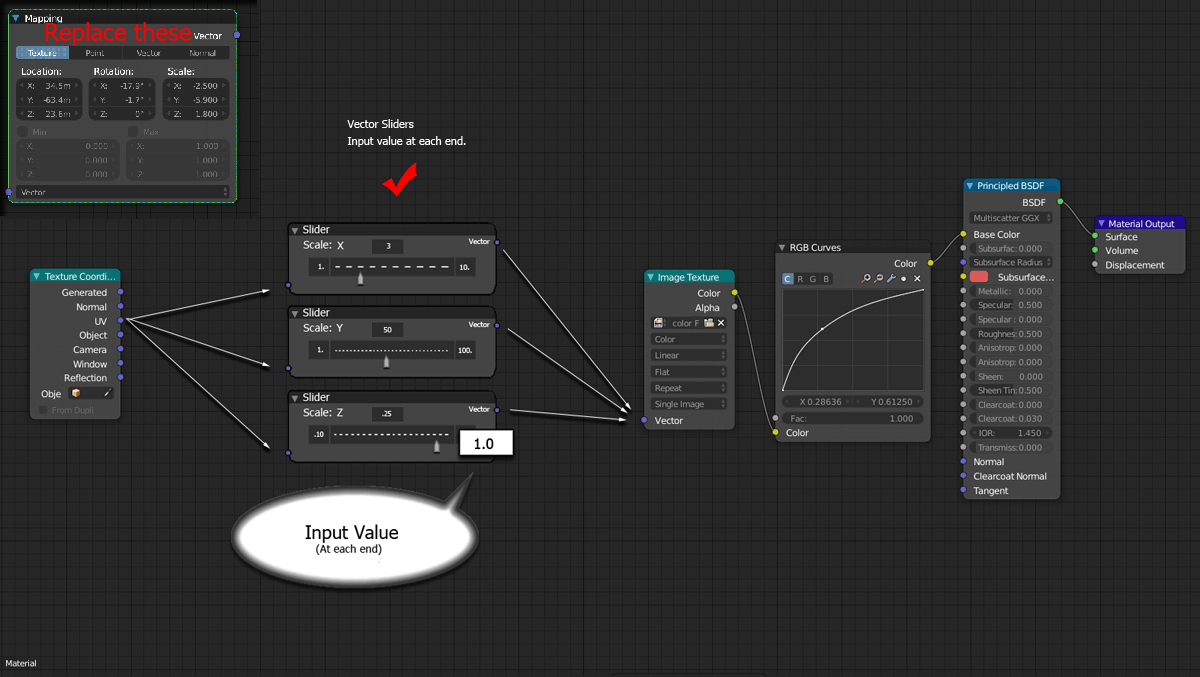
Based on my experience using NODES in Rhino & Grasshopper, I'd venture to suggest that BLENDER having a VECTOR SLIDER NODE in which you could write an input value at each end - for the min/max - to replace the MAPPING or plug into the Mapping Node. See Illustration.
My current configuration is here, and sliders (illustrated - not real nodes) would solve the problem, however, each folder in the Mapping Node would need a plug-in/out or a dedicated slider, per se, below is my current configuration:
Here's the nefarious Mapping Node which I mentioned...
@aliasguru answer is great, I went a little further and used quaternions to rotate textures, it works pretty good check it out: https://gum.co/zqFNO here's an image of it:
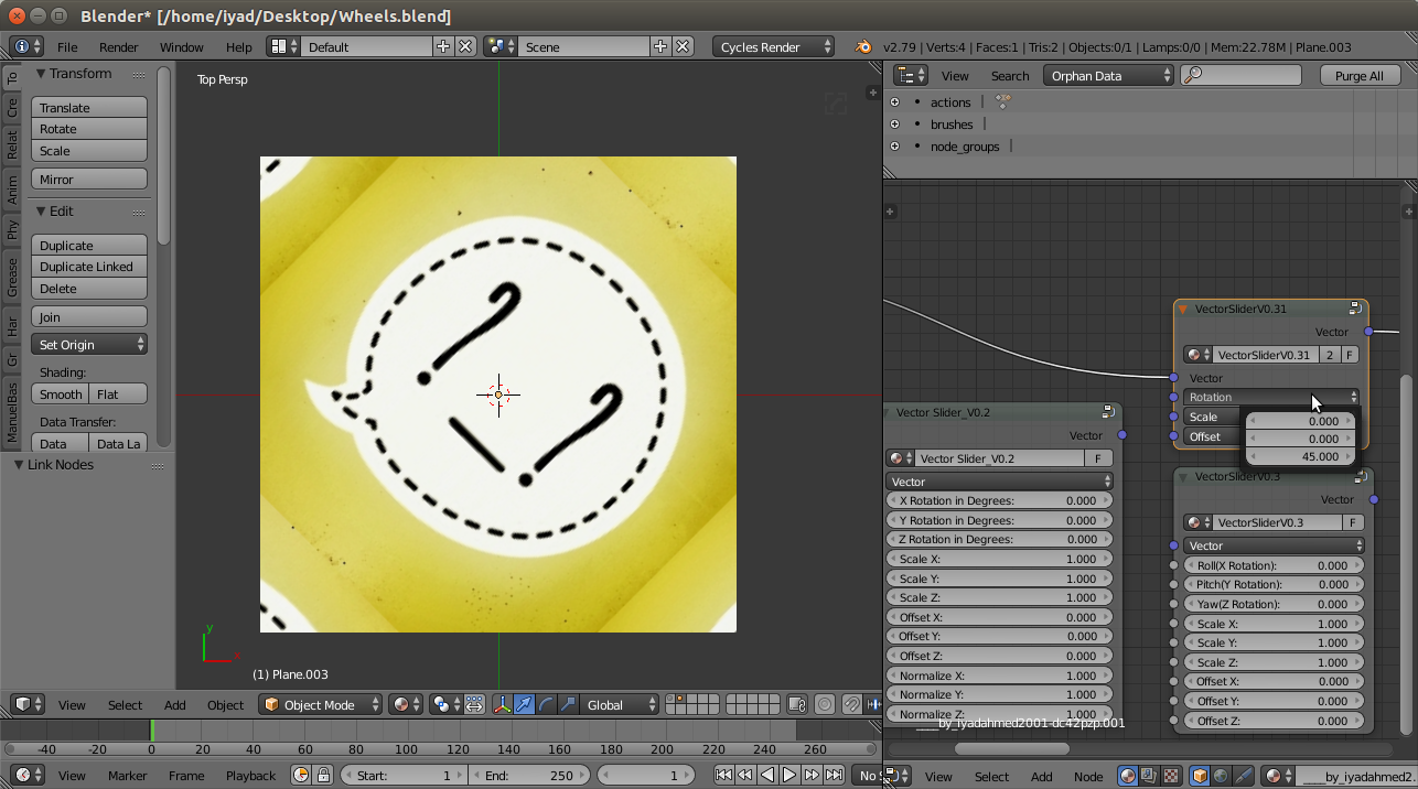 Image 1
there are 3 versions of the node group "VectorSlider":
V0.2: similar to @aliasguru answer, but suffers from gimbal lock, see this: https://en.wikipedia.org/wiki/Gimbal_lock
V0.3: uses quaternions works perfectly, no gimbal lock
V0.31: same as V0.3, just replaced 9 sliders with 3 vector input, you can change individual values by clicking the vector input(see image 1), also you can use "Combine XYZ" to control individual values(see image 2)
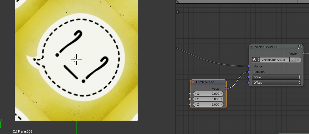
Image 2

