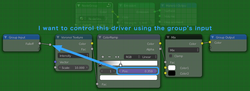
As far as I know, I don't think it is possible to drive a Color Ramp or Mapping nodes from another socket (but I am not super experienced in drivers). However I have managed to re-create the color ramp and mapping node with math nodes, which you can plug inputs into directly.
Color Ramp
Unfortunately there is no way to create a group node exactly like the Color Ramp, with addable and removable color swatches. To get around this I have created a node with two movable swatches, you can then combine multiple of these nodes together to have the functionality of multiple swatches.
The theory:
The two input colors are plugged directly into a Mix RGB node. The two Pos inputs need to be sent through a function and plugged into the mix factor. The position of the first swatch needs to be mapped to $0$ to get just the first color out of the mix node. The position of the second swatch needs to be mapped to $1$ to get just the second color out of the mix node.
The math:
Here's a graph to visualize what we are trying to do, on the x-axis is the input factor of the color ramp, on the y-axis is the desired output, $a$ and $b$ are the positions of the two swatches.
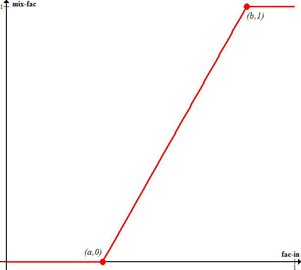
With some simple algebra we can find the equation of the line to be:
$$
y = \frac{1}{b-a}x + \frac{a}{a-b}
$$
The math nodes below are simply replicating this equation. The final Add node also has Clamp checked to clamp the output to the interval $[0,1]$, which is what the mix node accepts.

Mapping node
The mapping node has three functions it can Translate (move), Rotate, and Scale the texture. Since often not all of these are needed I will create separate group nodes for each of these functions.
If you don't have a decent understanding about how texture coordinates work you may want to read my answer here. The basic theory of manipulation texture coordinates is to separate the components of the vector with a Separate XYZ node, manipulate the components individually, then combine them back into a vector with a Combine XYZ node.
Mapping Node - Translation
Translation is easy, to translate $V$ to $V^\prime$ just add the desired amounts to each of the components of $V$.
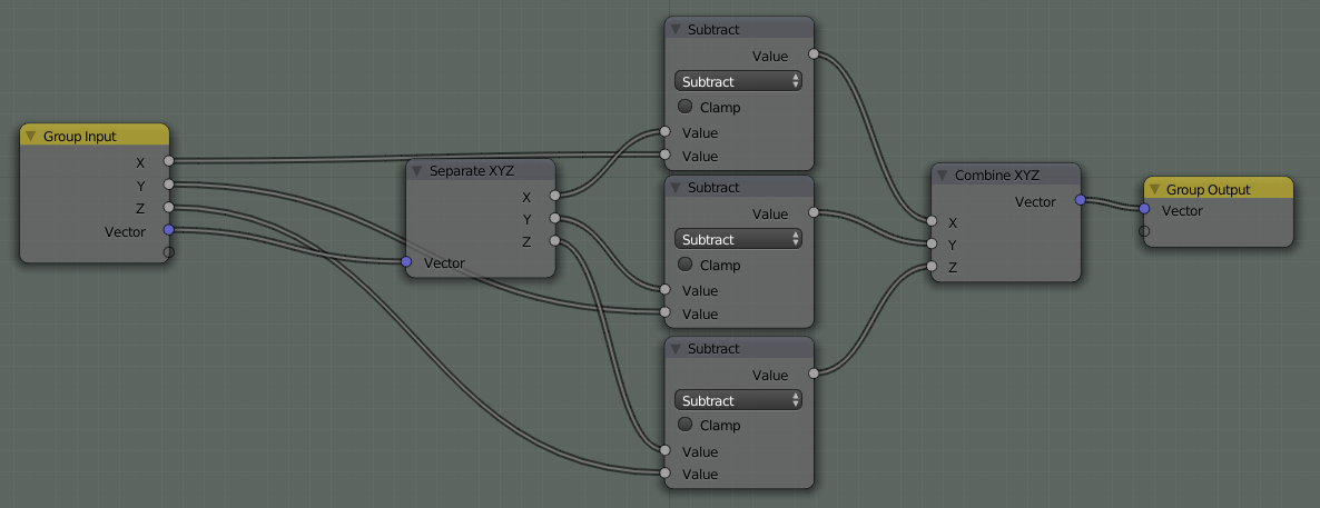
In the above node setup I actually used Subtract nodes instead of Add so positive values will move the texture to the right instead of left.
Mapping Node - Scaling
Scaling is the same as translating, just multiply the individual coordinates by the scale factor instead of adding.

Mapping Node - Rotation
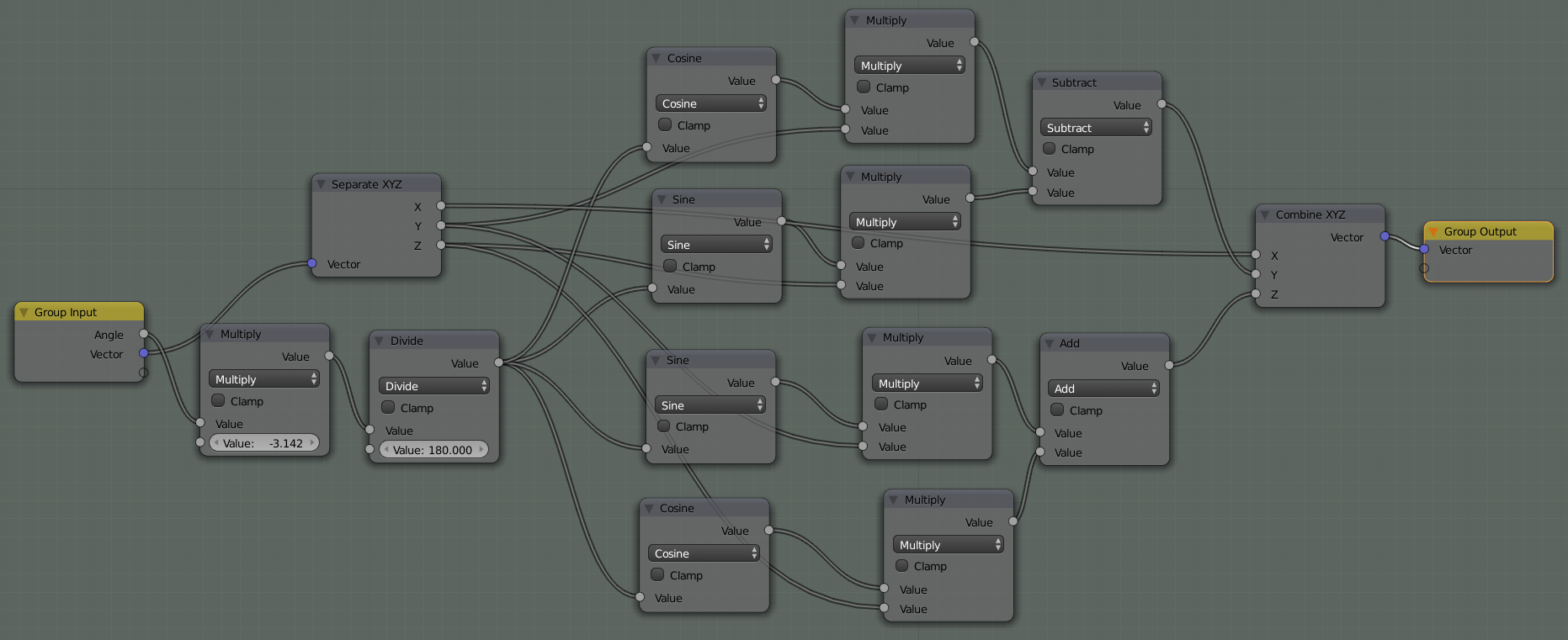
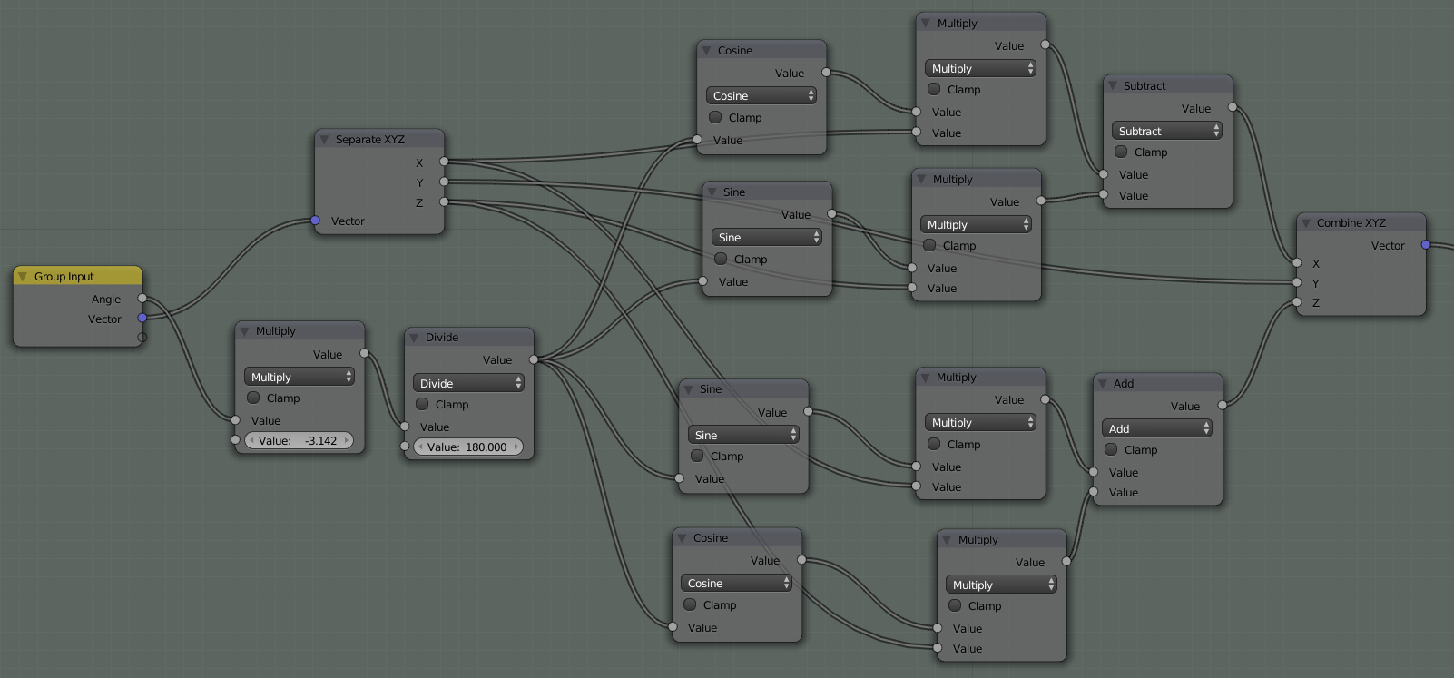
Rotation is a little more complicated and I won't take the time to derive the equations here, but they are pretty standard pre-calc formulas. Here are the formulas for rotation.
Around the x-axis
$$
\begin{aligned}
x^\prime &= x\\
y^\prime &= y\cos{\theta} - z\sin{\theta}\\
z^\prime &= y\sin{\theta} + z\cos{\theta}
\end{aligned}
$$
Around the y-axis
$$
\begin{aligned}
x^\prime &= x\cos{\theta} - z\sin{\theta}\\
y^\prime &= y\\
z^\prime &= x\sin{\theta} + z\cos{\theta}
\end{aligned}
$$
Around the z-axis
$$
\begin{aligned}
x^\prime &= x\cos{\theta} - y\sin{\theta}\\
y^\prime &= x\sin{\theta} + y\cos{\theta}\\
z^\prime &= z
\end{aligned}
$$
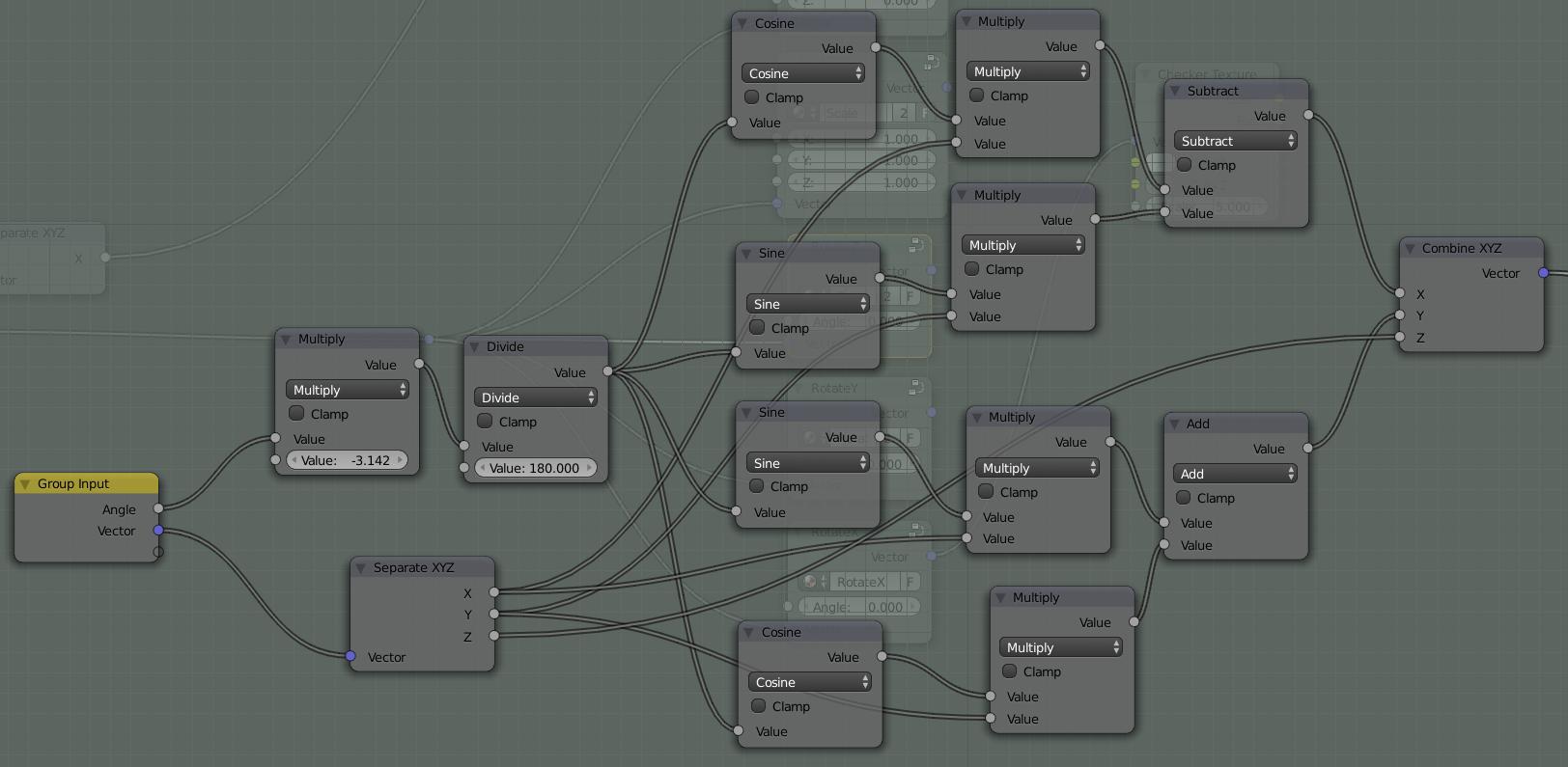
Note: the first two nodes in each of the rotation setups convert the degree input to radians, which is what the trig math nodes want.
And finally, here's a .blend file with all the above node groups.


