16
$\begingroup$

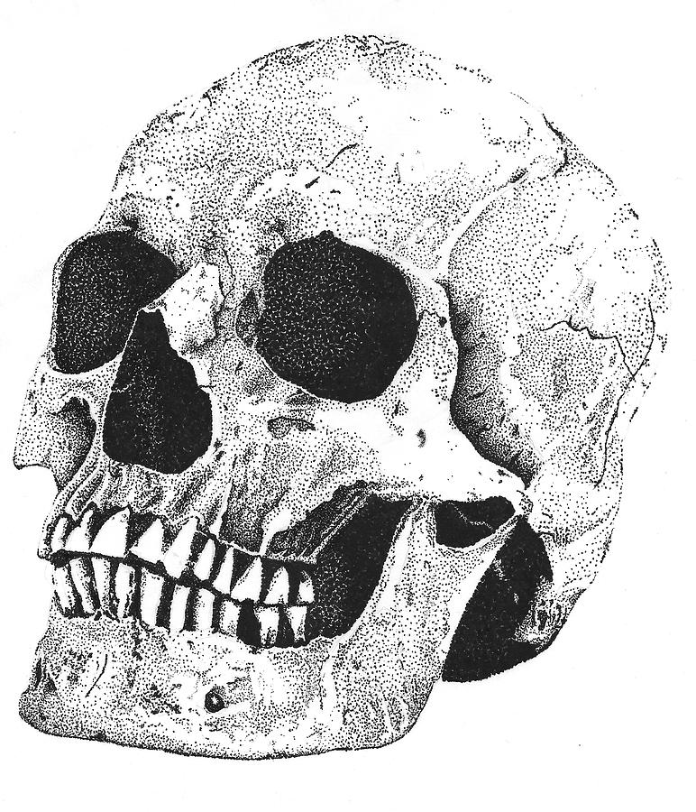
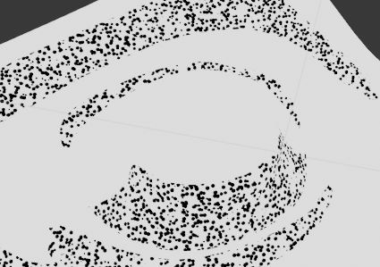
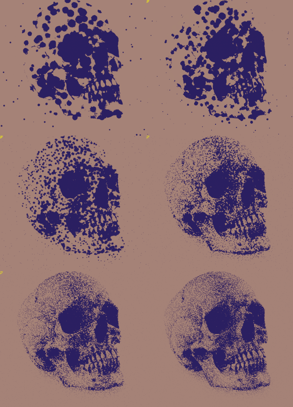
I have had this idea for a little while, using Blender to simulate traditional stipple shading. I have gotten an OK effect using a mix shader with ambient occlusion as a factor to spread a stipple texture in the cracks and crevices of objects. The main problem with this is that all the dots are evenly spaced, and the dots fade out while on a real stipple shaded painting the dots are very closely spaced towards dark areas and get sparser as it gets further away from those areas (see attached image). I'm pretty stuck on how I could produce this effect, I have been thinking there might be some way to control the clustering of a voronoi texture using ambient occlusion, but that's just an idea. Does anybody know of a way to simulate stipple shading? Please advise.

If you don't know how to replicate stipple shading, but you feel like you have some ideas or tricks you think could be useful, please comment, I'll try them.

enter image description here

$\endgroup$
6

4 Answers 4

18
+300
$\begingroup$

This is a procedural shader-only approach, which could be adapted to taste. It's based on capturing the light-response of a surface as a color, and deciding on a set of threshold values in its brightness. For each threshold, darker tones are uniformly textured with procedural dots. The resulting textures are layered over one another, so tones below the minimum threshold get all the layers, the second-lowest all but one, and so on.

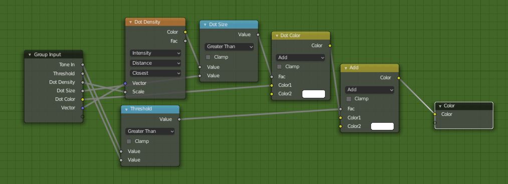
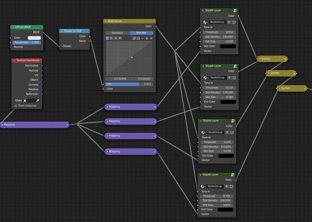
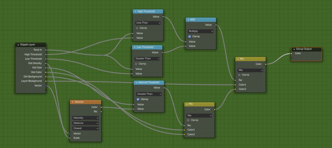
Create a 'Stipple Layer' node-group which will texture everything below a given brightness with procedural dots.

enter image description here

  • The Dot Density node is a relabeled Voronoi texture: the larger its scale, the further apart the dots.
  • The Dot Size node is a relabeled Math > Greater than node: it determines the internal threshold on the Voronoi texture. Below the threshold, the dot will be Dot Color, above it, white.
  • The Threshold node is the external threshold value. Below it, there will be dots, above it, white.

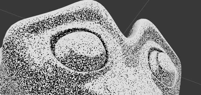
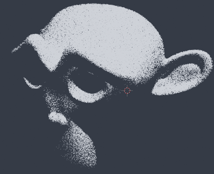
Suzanne's eye trough a single one of these groups would look something like this, depending on the settings:

enter image description here

Now to layer them up.

enter image description here

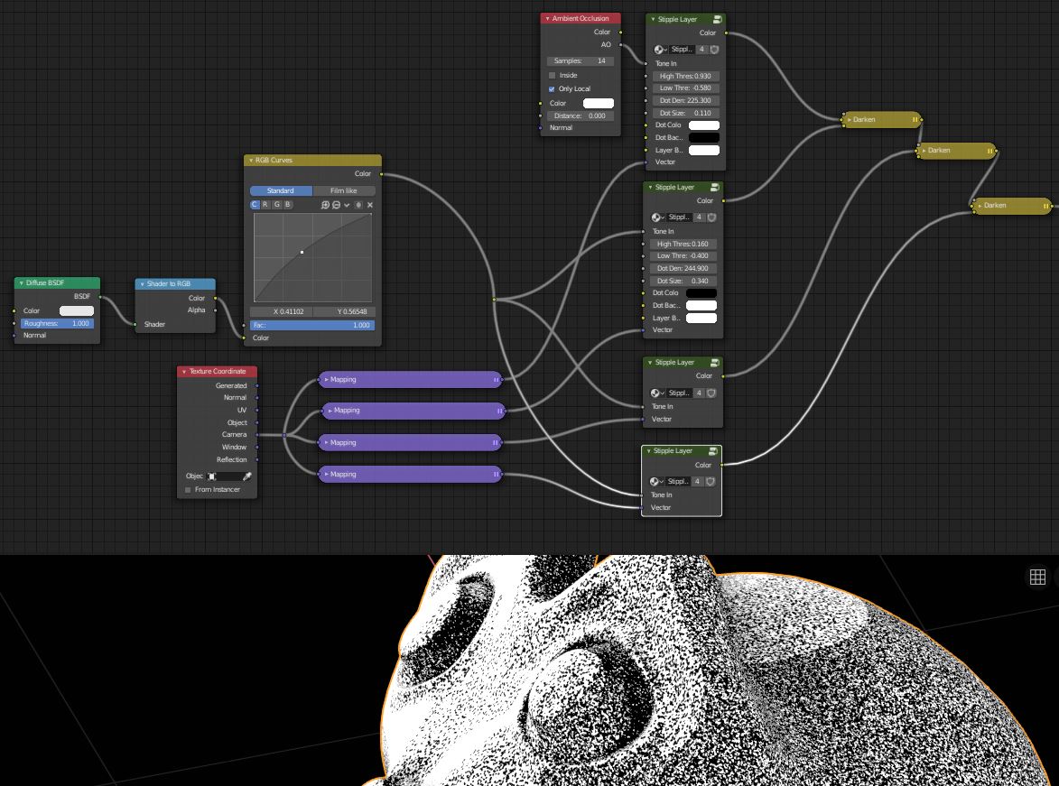
  • Suzanne is shaded with a diffuse shader, and then the color extracted trough a Shader to RGB node. This means you must be in EEVEE, or just tap the color out after shading in Blender Internal, pre-2.8. Cycles doesn't know what the color of a surface is, until all the rays have been integrated at the end of rendering. Too late for us.
  • The RGB Curves node allows overall adjustment of brightness and contrast. 'Brightness EQ'
  • Unless each Stipple Layer group gets its own Mapping node, all the dots in the layers would be exactly over one another, so there would be no shading. Each mapping node is set to translate the texture by some arbitrary long way, so the lookup comes from different places in texture space.
  • Each layer darkens the next, so the dark dots accumulate over the white background.

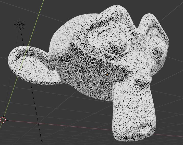
The result of 4 layers:

enter image description here

By tweaking the dot sizes, densities, and thresholds, the boundaries between the layers can be disguised quite well. You can add an Ambient Occlusion shader to feed a layer, and intensify crevices, if you like:

enter image description here

You could also for example, split out your own R,G,B, and (probably) brightness channels to do a home-brewed color separation... lots of options.

The Dot Size and Dot Density entries interact: If you adjust one, you have to adjust the other to compensate. You could perhaps automate that relationship? : I tried a simple division - it wasn't quite linear, and wound up being easier to adjust by hand.

Suggestions for improvement welcome.

Edit: I've expanded the group a little to include more options:

enter image description here]6

  • An upper and a lower threshold of input tone for a stipple layer
  • 'Dot Background': a background color for the zone between the thresholds
  • 'Layer Background': a background color for the zone outside the thresholds

These allow the possibility, for example, of negative layers (white dots out of black).

enter image description here

Version 1:

Version2:

$\endgroup$
11
  • 2
    $\begingroup$ I tested something similar when thinking about this question, but there is significantly more variation in size of the dots made with voronoi than there is in the sample image and I think this will always fail to replicate the look because of that. Also I have searched for reference images online and found many examples where the shading gradients are way finer than a few layers. I think an image texture and a lot more layers should be used to achieve better results. $\endgroup$ Commented Jun 30, 2019 at 14:25
  • $\begingroup$ @MartinZ Agreed. .. and more importantly, the distribution is not random.. it helps the modelling along. Even with an image texture you'd still have the problem of overlapping dots. Particles? I've been looking at this kind of thing for a while.. trying to get hatching to follow principal curvatures.. it's been done, of course, but not in a way I can think of imitating in Blender. $\endgroup$
    – Robin Betts
    Commented Jun 30, 2019 at 14:38
  • 1
    $\begingroup$ @cegaton .. don't I know it :) ..yes, I would love to see a better solution than this one. Maybe shouldn't have been accepted so soon. I'll have a pop at that option when I have some uninterrupted time. I'm also getting some greys out of EEVEE that I don't understand yet. Not very experienced with EEVEE, $\endgroup$
    – Robin Betts
    Commented Jun 30, 2019 at 17:50
  • 2
    $\begingroup$ Processing the image as a texture with material nodes may achieve better results. I think a spherical gradient(so the size can be controlled later) could be distributed modifying its coordinates with math. But that would probably be lots and lots of math. No matter how fun that sounds, I am not willing to go there... I am out of ideas in Blender. I would give up and use something like github.com/evil-mad/stipplegen/releases/tag/v2.31 $\endgroup$ Commented Jun 30, 2019 at 23:36
  • 2
    $\begingroup$ @RobinBetts I'm happy to put out more bounties (what else is there to do with reputation points?) $\endgroup$
    – user1853
    Commented Jul 4, 2019 at 22:10
15
$\begingroup$

Here's my take on this - for what it's worth. This solution is quite similar to Robin Betts' answer but making more use of the other Veronoi properties (the additional 2nd, 3rd, 4th closest cell distances and colours, available at Blender 2.8) in order to avoid having to 'layer' multiple textures and to use the Cell color to hide some of the 'points'.

The nodes used for this are as follows :

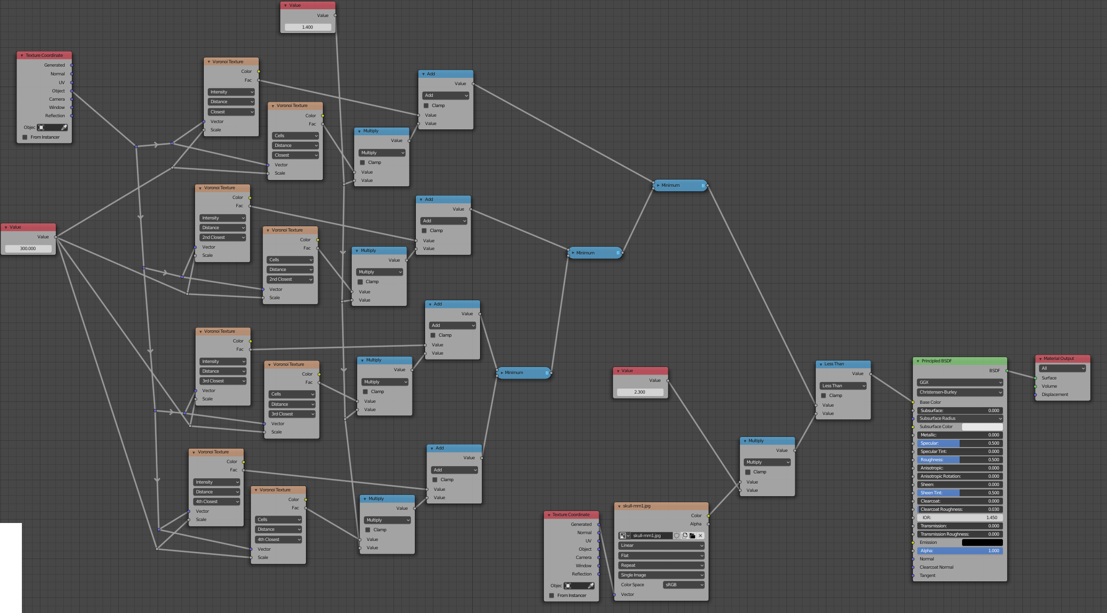
material nodes

Note how there are 4 pairs of Voronoi Texture nodes. Each pair has one set to Intensity (to get the distance to the centre of that cell) and the other set to Cell to get its color. Each pair is set to a different cell centre (Closest, 2nd Closest, 3rd Closest, 4th Closest) so as to get the properties of the closest cell (the one the sample point is within) and the three adjacent cells. By combining the Intensities (distances) we can get the minimum distance to any of those cells, and this allows us to effectively have "overlapping" cells since the 'circles' are no longer limited to the edges of the individual cells. The 'Color' of each cell is combined with the 'Distance' so as to be able to randomly offset each cell - so that when we use the Less Than to determine if we're within one of the 'stipples', we effectively "delay" some of the cells from appearing, allowing the density to be adjusted (by changing the input to the Multiply nodes).

The Less Than nodes compares the point from the image with that of the distance to the closest cell (after the random variation based on the cell color has been applied) to grow each cell based on that part of the image.

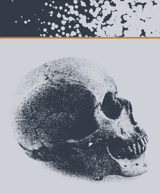
This can produce the following result :

result

(the band at the top shows the progressive increase in intensity from left to right and how it affects the stippling)

The node tree provides three inputs - the Scale (leftmost 'Value' node) to scale the 'dots'), the "brightness" (centre 'Value' node) to change the brightness of the image (varying the overall dot sizes) and the 'stipple delay' (changing how much the cell 'random' color affects the 'delay' before that particular stipple becomes visible). Vary those three inputs to get the desired effect.

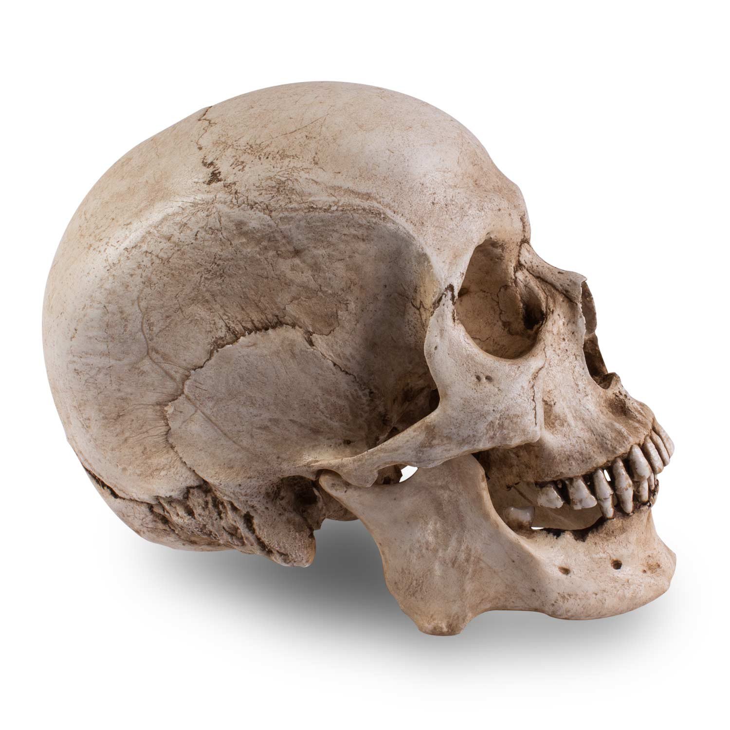
The source image in this case was the followng skull image found from a quick Google search - but you could use any rendered image or use a technique to sample directly from the shader as described in Robin's answer.

source image

Blend file included

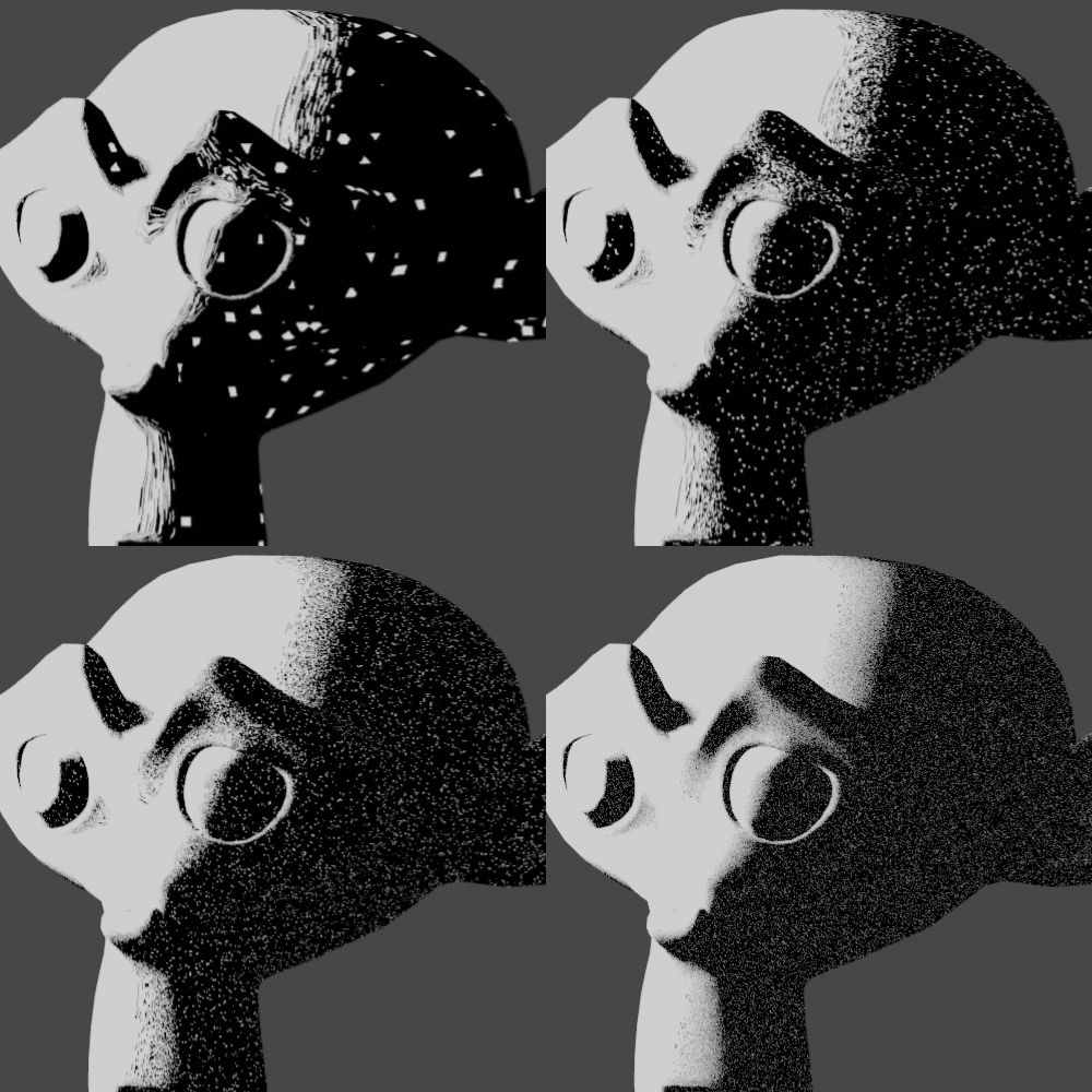
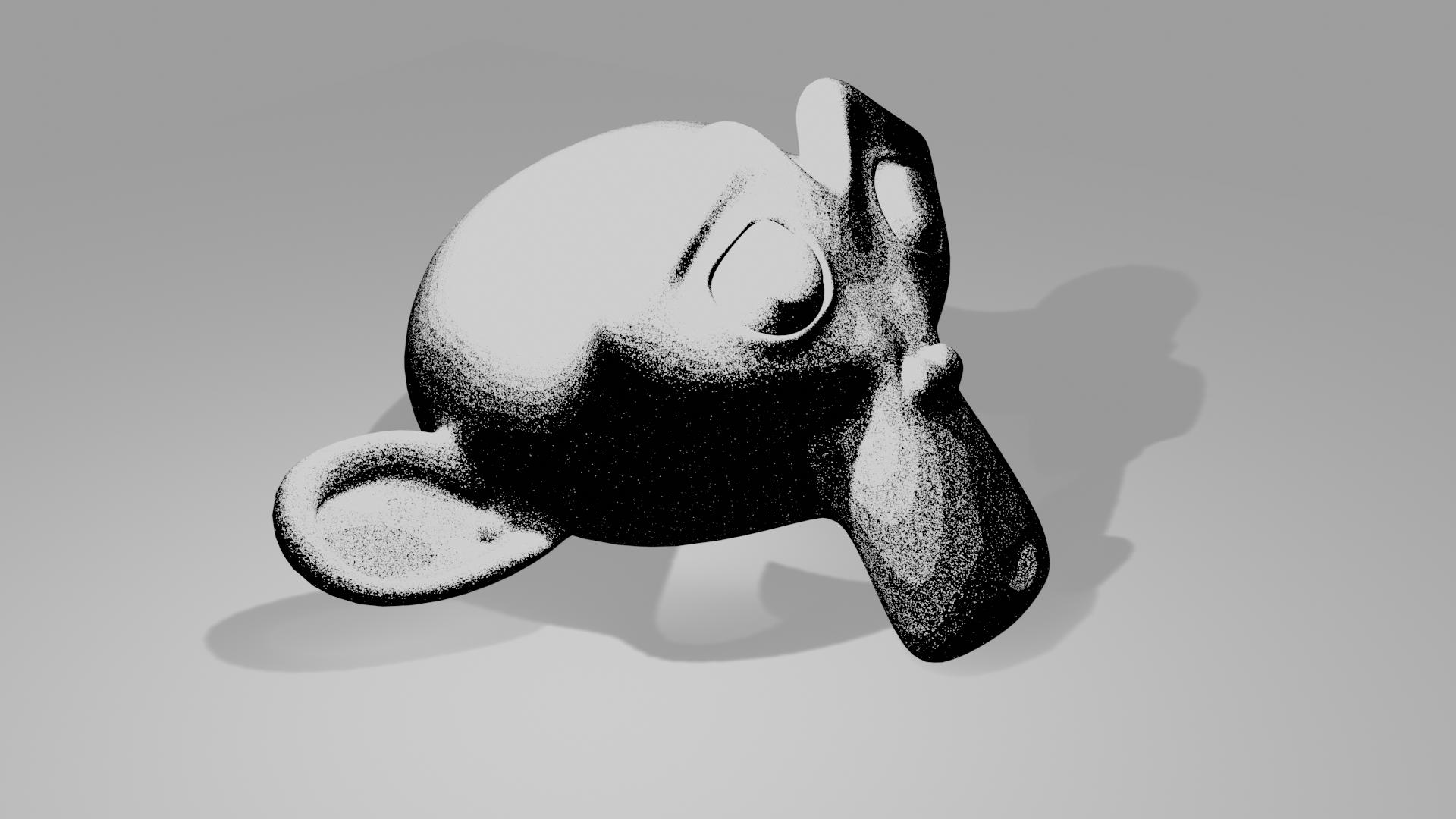
For completeness, here's the effect on a rendered Suzanne :

suzanne stippled


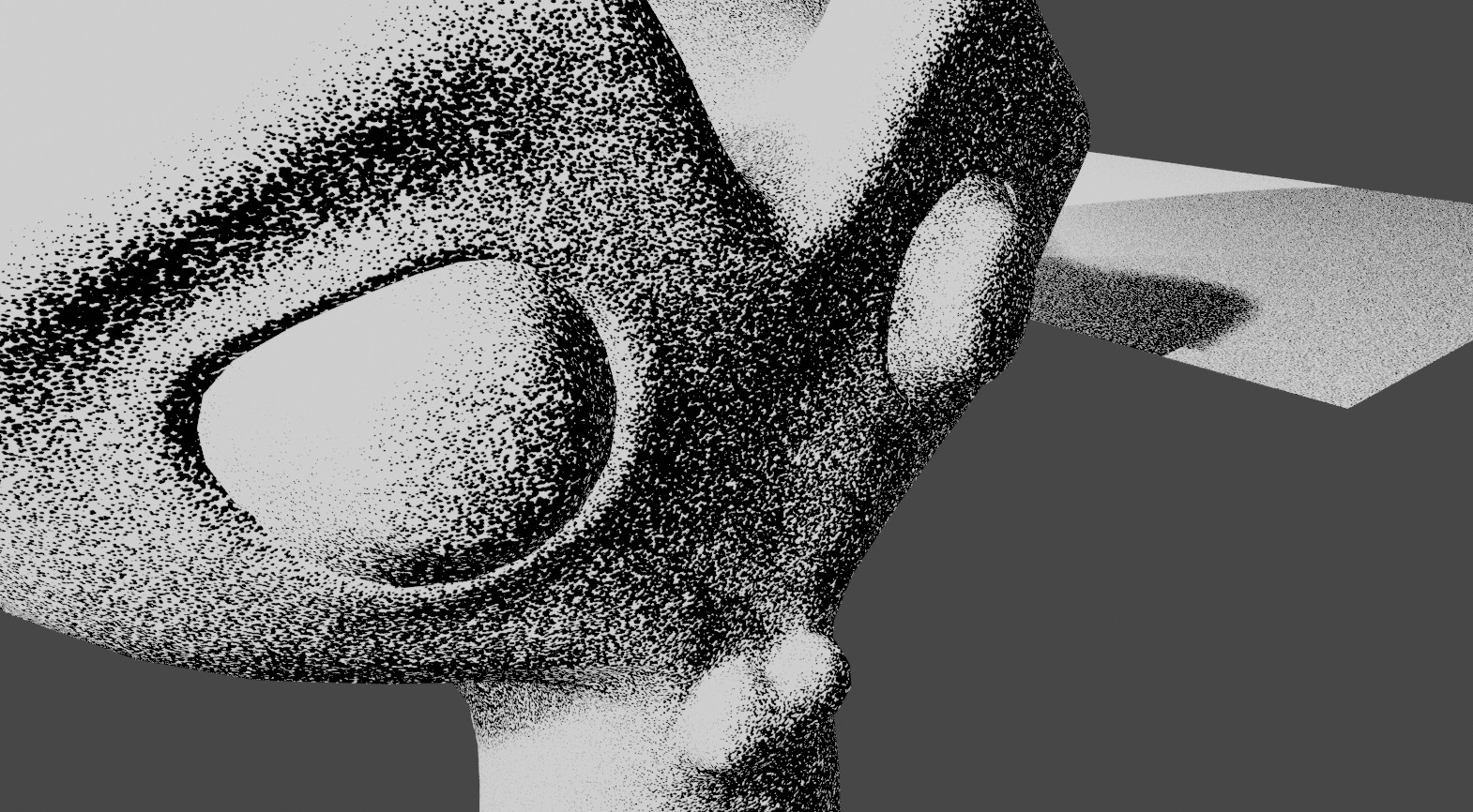
EDIT: Here's an example using ShaderToRGB to produce a 'live' shading (rather than from an image). I've also added in a Modulo function to cut the shading into distinct 'bands' similar to your original sample image.

suzanne stippled2

$\endgroup$
2
  • 2
    $\begingroup$ Arrrgh! I wish I could split the bounty on this.. you and @lemon have both put so much into it.. and I've had to be afk at just the wrong time to really get under the skin of your answers. As usual, (for me, anyway) yours is more than an answer to this particular problem. It opens up other possibilities by giving a better understanding of the tools. I'm still holding out hopes of using the dx & dy OSL ( x and y are in screen space?) functions to extract some information about the curvature of the surface .. but it's a way off for me, if it's even possible. $\endgroup$
    – Robin Betts
    Commented Jul 11, 2019 at 17:44
  • 2
    $\begingroup$ @RobinBetts Don’t worry about the bounty - by all means award it to lemon as I think that answer is more deserving. I’m intrigued about extracting the curvature and using that to shade the surface - perhaps this would be better suited to compositor rather than shader using the Normal pass; that’s certainly something to think about. Perhaps using Freestyle to capture the edges also. $\endgroup$ Commented Jul 11, 2019 at 18:02
8
$\begingroup$

What I've tried to do here is:

  • Making black dots of constant size but placed in a blank of various sizes
  • These sizes are shadow intensity dependent
  • Dots are shuffled to avoid too much regularities
  • One can adjust the scale (shadow intensity to an amount of discrete value) and the resolution (the size of the dots)

The result is not perfect (especially I would like thinner dots more regular and more spaced) but if that can allow to go further for someone...

As said there is two main parameters to play with:

  • Resolution (the size of the dot)

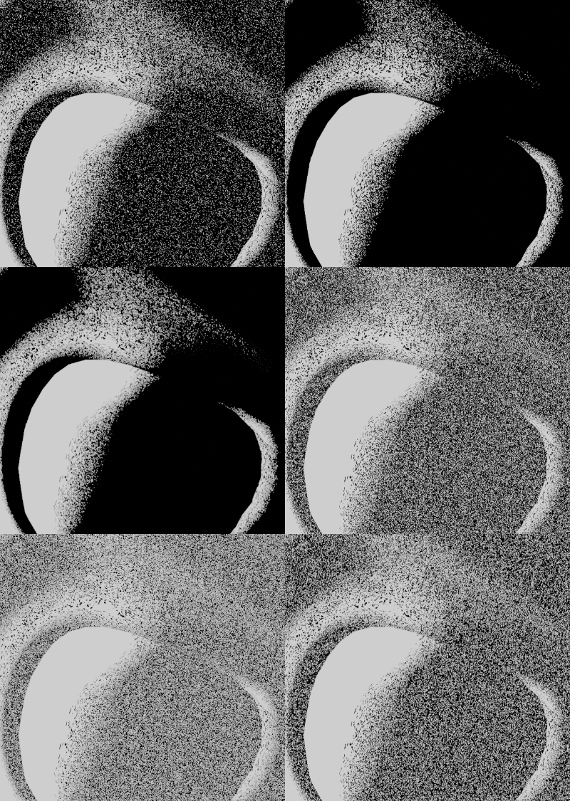
enter image description here

  • Scale (the overall 'sampling' rate)

enter image description here

Preamble

Node groups:

  • StepValue and StepVector

Rounds a value or a vector at a given resolution.

  • ReportValue and ReportVector

Just make copy of the input but facilitate the node placements

  • DiffuseToBWScaled

Captures the shadow value. It uses a diffuse shader convert to rgb then to black and white. This result can be scaled to a given input.

  • VectorFromValue

Create a vector X = Y = Z = the input value.

Input

Can be either 'generated' texture coordinate or a variant based on 2 UV maps mimicking 3D coordinates.
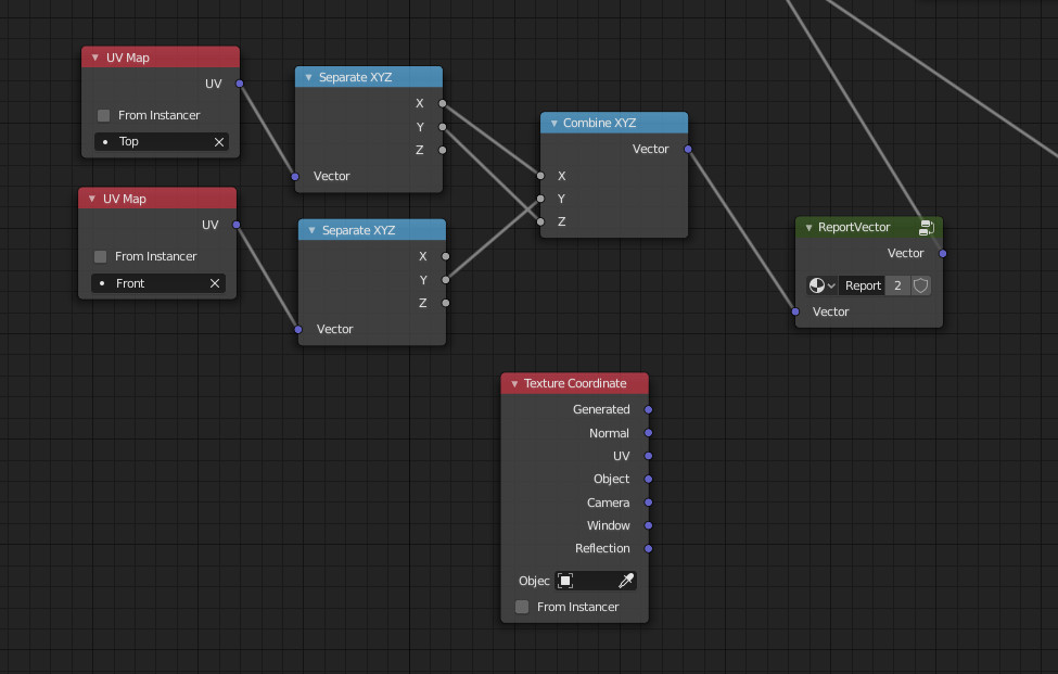
enter image description here

Shadow

Some kind of shadow catcher which is inverted and set to a given resolution/samples (here 60).

The result is multiplied with the overall scale (upper part on the right) to feed the part that makes the dots.

And the result is also given to the shaders so that it can filter where the shadow (dots) is to be applied (bottom right part). This output is strictly constrained by the colorramp so that there is not grey output (as we want a 'pure' black or white result).
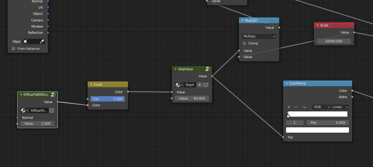
enter image description here

Shuffle

Take the input coordinate and samples it at the (shadow intensity * the scale). Then take a random value which is reported as a vector.
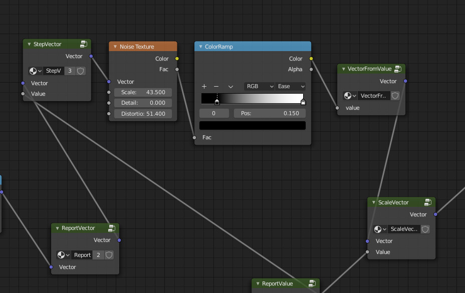
enter image description here

Dots

The 'dots' part calculates a radius from a sampled area (area size is 'scale' relative size).

The result is compared to a threshold radius ('resolution') which size it itself relative to the 'scale'.

The result is used to output black inside the dot and white outside.
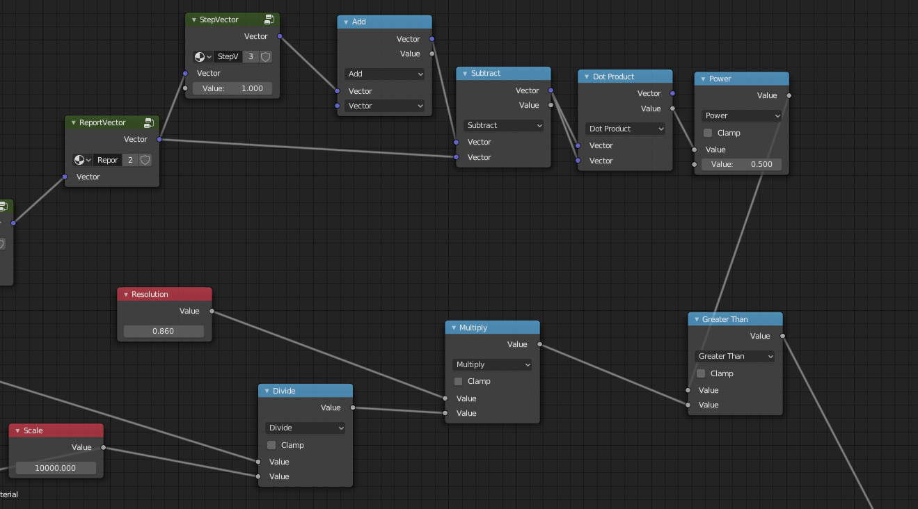
enter image description here

Shader

The shader is in two steps.

Make the dots using a mix shader factor from the 'dots' part above.

Make the 'shadow / non shadow' region using a second mix shader with a factor coming from the 'shadow' part above.

Only colors are used because we don't want additional shader effects here.
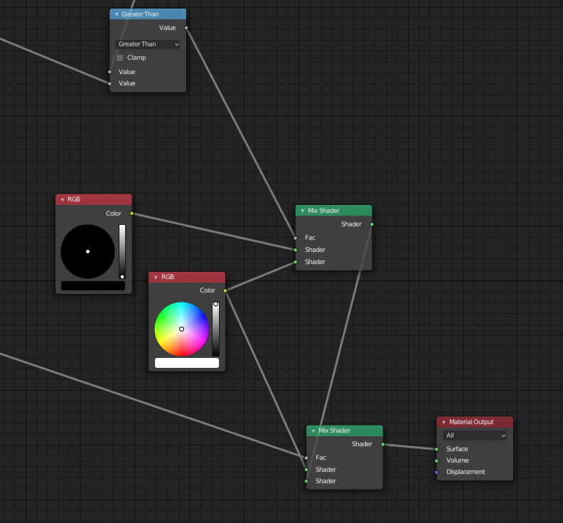
enter image description here

Done with Eevee (2.8).

Edit: a variant using Voronoi

This alternative setting uses the same principles but replaces the 'dots' part above with the following setting using a Voronoi texture.
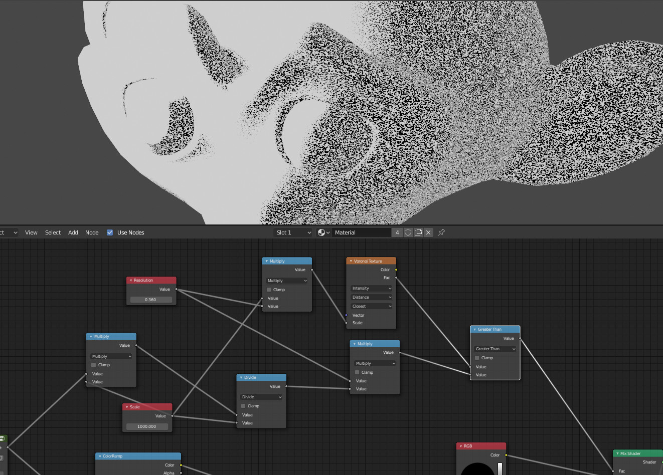
enter image description here

Depending on the 'scale' and 'resolution' value, it could allow result that are closer to the skull image in the question.
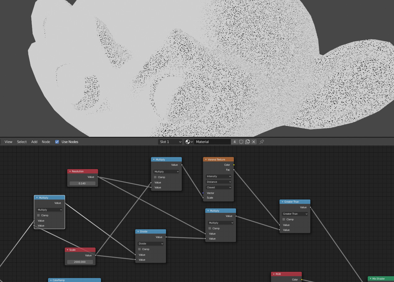
enter image description here

$\endgroup$
1
  • $\begingroup$ Brilliant, your work is amazing. I can see how one can easily turn your grains into watercolour painting. $\endgroup$ Commented Jul 6, 2019 at 21:43
5
+300
$\begingroup$

Another solution (from my previous one). It has the same disadvantages, but is really simple. I present it separately for clarity purpose.

enter image description here

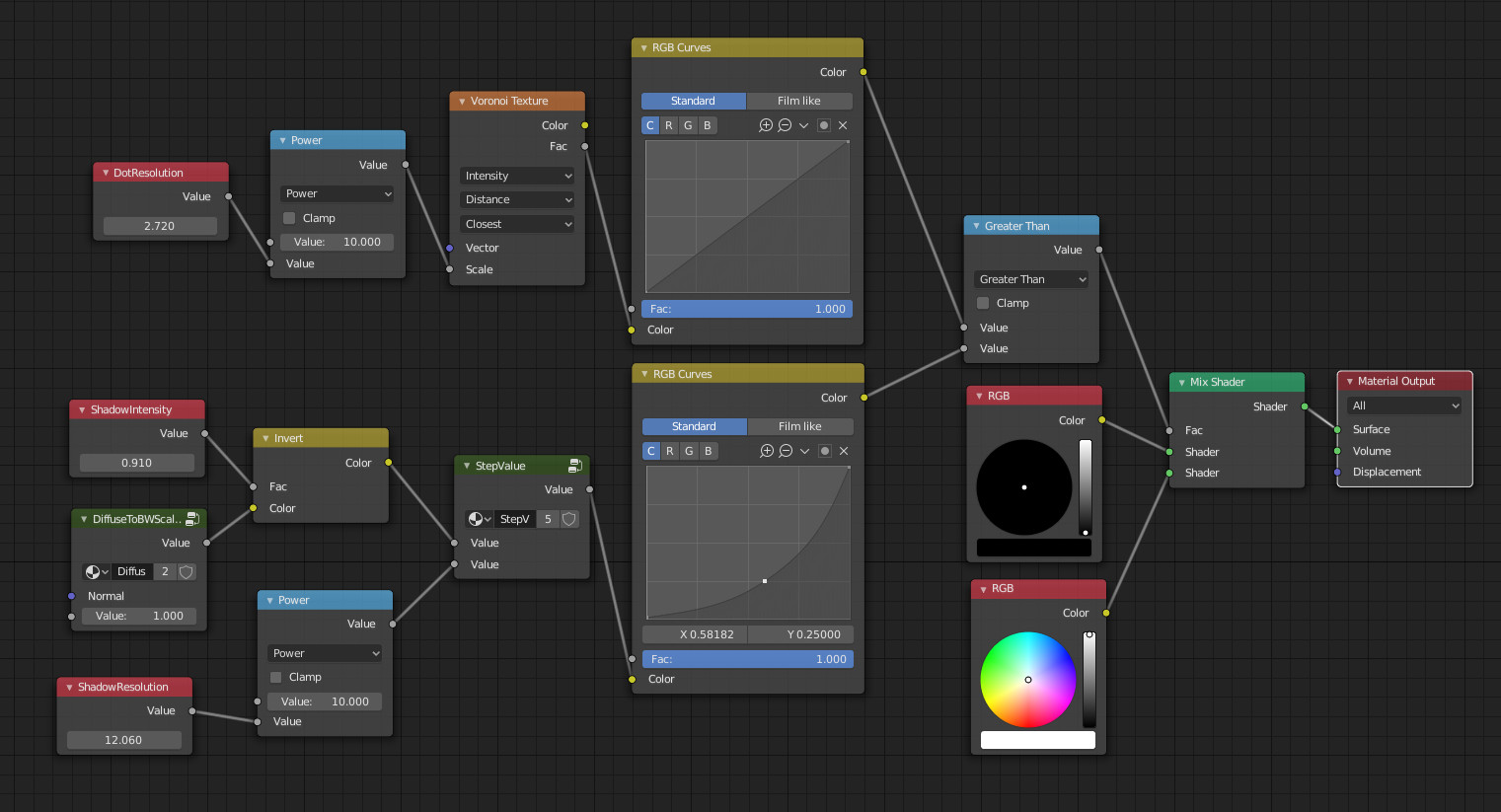
The setup:

enter image description here

It mixes a Voronoi texture with a tunable dot resolution with the shadow intensity.

ShadowIntensity node influences a shadow intensity catcher which is into DiffuseToBW node group.

The shadow resolution (gradient step) can be tuned using 'ShadowResolution' input.

Voronoi and shadow inputs can be influenced using curves to tune the effect.

Then depending on the comparison ('greater than' node) we display black or white.

What is not solved (that's the main difficulty, surely) is how to have both regular dot size and make so that they are placed a bit randomly.

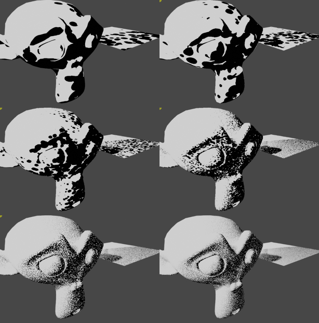
Dot size

enter image description here

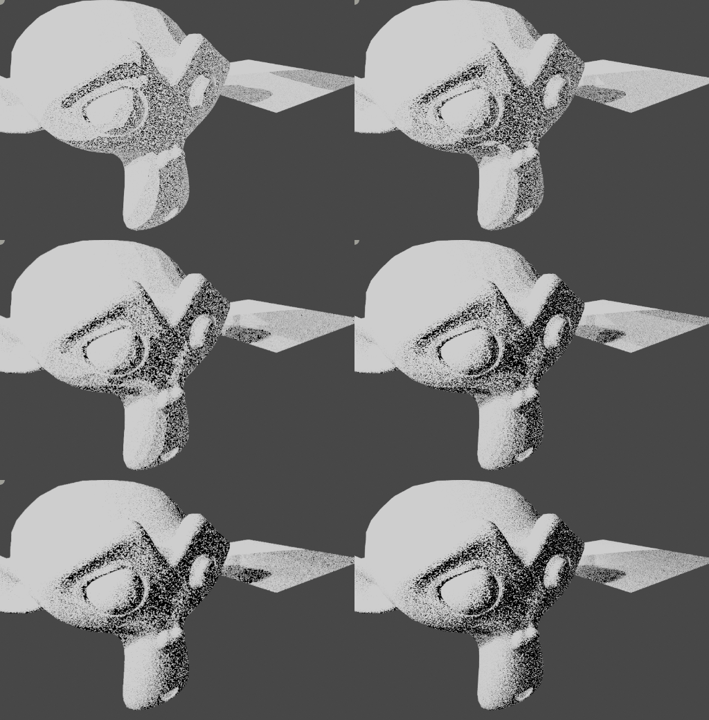
Shadow levels

enter image description here

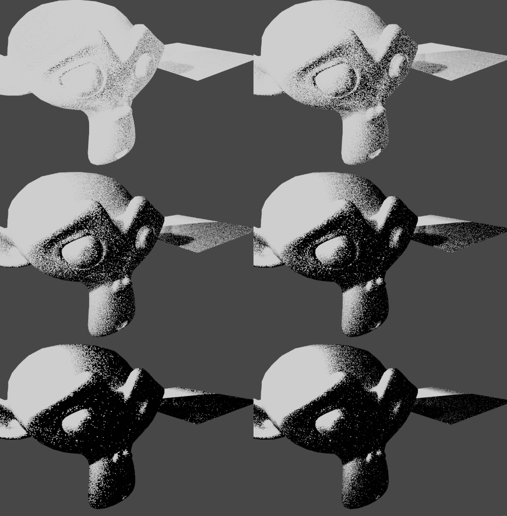
Contrasts

enter image description here

Inputs from a texture

Replacing the shadow level input node by a texture, you can have the following result:

enter image description here

$\endgroup$
10
  • $\begingroup$ As I commented on @Rich Sedman's answer, I wish I could split the bounty.. I've had to be away.. I haven't had the time to take your answers apart in serious way.. yours has a half-toning element (tone>dot size) ..that, and using a texture, does look the way to go to get away from the signature, sandy. 'noise' rather than 'stippling' effect.. although to tell the truth, neither really feels like stippling, without the modeling a human draughtsman would give it... anyway .. yours on the basis of aesthetics.. closer than either of our answers, IMO.. $\endgroup$
    – Robin Betts
    Commented Jul 11, 2019 at 18:05
  • $\begingroup$ @RobinBetts. Thanks. I'm aware that all answers are far from a human made result. I've searched a lot for a way to make it starting from a texture containing one drawn stipple (so that we could have dot, cross, or anything). But this is still work in progress and so far is a very complicated node setting mimicking a convolution + some random effects. Did not published it here as the results are not what I expected. If I've time to make progress on it, I will post it as additional answer so you can be informed. $\endgroup$
    – lemon
    Commented Jul 12, 2019 at 5:46
  • 1
    $\begingroup$ @RobinBetts, this could interest you blender.stackexchange.com/questions/146140/…. It will not replace the stipple (as there is no density variation here), but... $\endgroup$
    – lemon
    Commented Jul 24, 2019 at 8:26
  • 1
    $\begingroup$ @RobinBetts, I've spent the morning on it to discover after that it is a duplicate question... so I deleted it. But here is the file if you're interested in it: blend-exchange.giantcowfilms.com/b/6293 $\endgroup$
    – lemon
    Commented Jul 24, 2019 at 9:27
  • 1
    $\begingroup$ That sounds very promising. perhaps my unconscious anticipation of the pain prevented me from thinking of it ... :D $\endgroup$
    – Robin Betts
    Commented Jul 24, 2019 at 17:00

You must log in to answer this question.

Not the answer you're looking for? Browse other questions tagged .