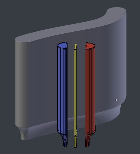
I'm trying to model a part that has a (helical) milled groove using the boolean modifier and can't find a good way to model the cutting path of the bit. I have tried using the screw modifier but this doesn't work well with 3D shapes. If I use the profile of the bit then it gets pretty close but doesn't quite replicate the final cut the bit would produce.
...........................
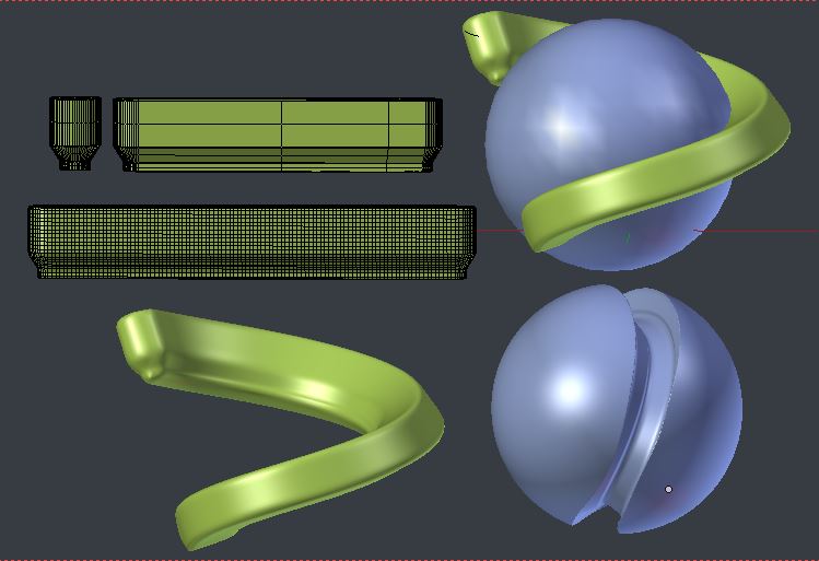
In this image I used the screw modifier both on the 3D shape and the profile. The best part of the screw modifier is that it extrudes to the next step which prevents visible steps creating a smoother result. The problem is all the interior faces / vertices it creates with 3D shapes. Also the face normals go wonky.
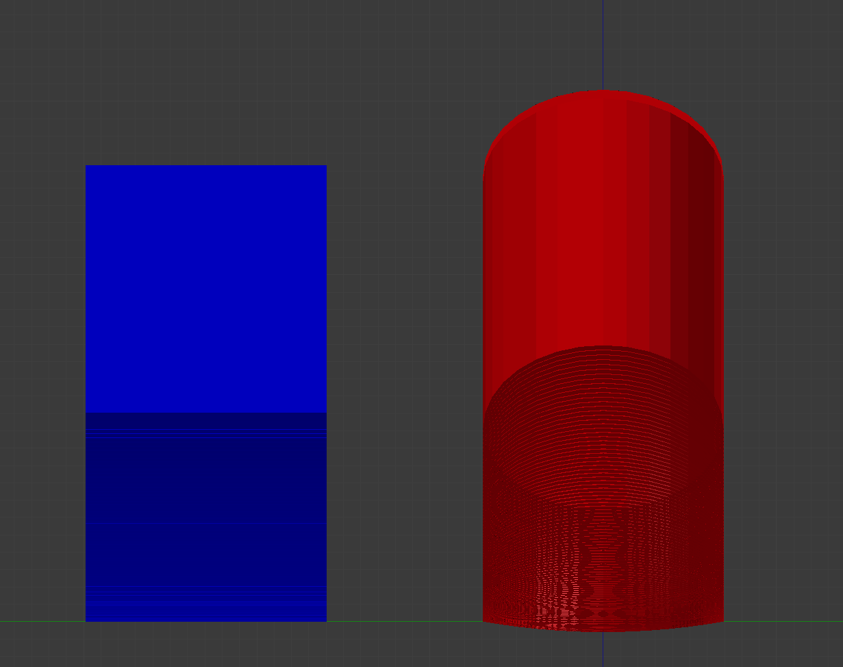
This image uses the array modifier + object offset set to an empty rotated 1 degree and shows the difference between the profile (of the cylindrical bit which amounts to a rectangle)(Left-Blue) and a full cylinder (Right-Red).
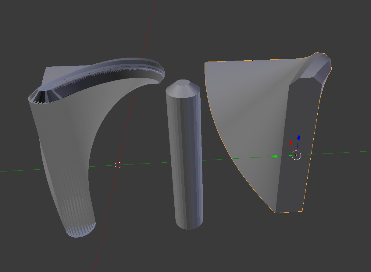
This image is to help visualize the problem. At each "step" of bit movement the removed material has to match the full shape of the bit or the final cut won't match what is actually happening.
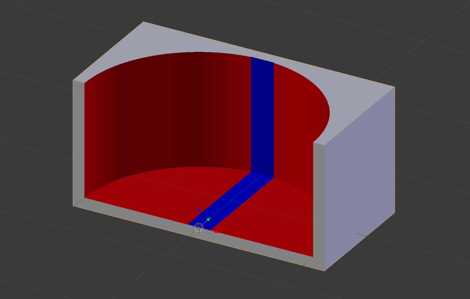
The closest I can probably get is to use the array modifier, P-Key->Separate loose parts. Then Union Bool to a final shape. Obviously that's an incredibly tedious process if you're trying to get a high resolution result by using more steps.
I may write a script for this and will definitely share and link if it works. But I've seen some really clever and elegant modeling solutions on here so hopefully someone has an interesting way to reproduce this type of machining operation.

