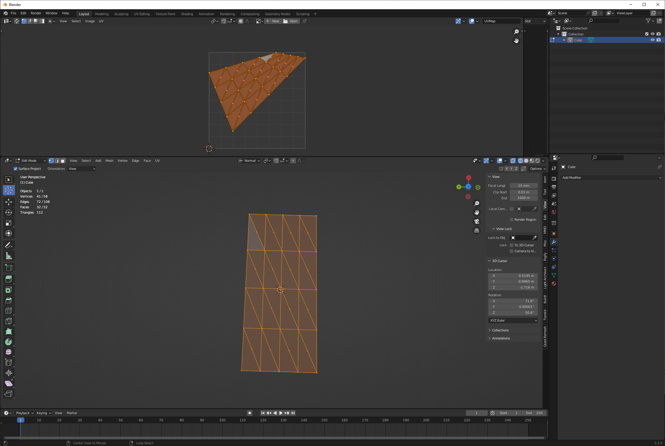
2
$\begingroup$

I'm using the UV project modifier to project an image from a projector. This projector is also a camera with the coordinates obtained using fSpy. Blender stackexchange user Cegaton taught me how to do this in this post using blender 2.8. I've had a few crashes with blender 2.8, so I am still using 2.79b.

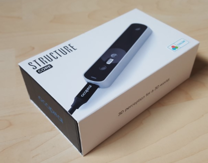
The image on the mesh in Blender 2.79b file is warped. See the original image below.

enter image description here

See the result of the UV Project modifier below. enter image description here
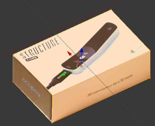
You can see that, near the red arrow, the image is warped/skewed. Also the texts are not straight.

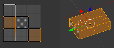
I unwrapped this box using Smart UV Project with default settings. I selected the faces on the UVmap that corresponds to the 3 faces that the image is projected on. enter image description here
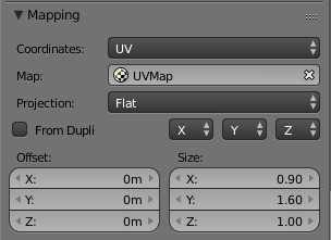
These are the mapping settings of the texture on the material.

enter image description here

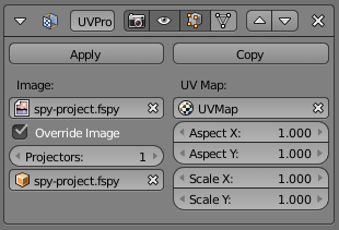
And here the settings of the UV Project modifier.

enter image description here

How can I make the image on the box look the same as the original?

Side note: I want to use the UV Project modifier as I want to apply this same technique to a room that was scanned to a point cloud and turned into a mesh. So for that I cannot use manual UV unwrapping, as it is too time consuming.

$\endgroup$
6
  • 2
    $\begingroup$ Add a few subdivisions to the mesh. $\endgroup$
    – user1853
    Commented May 26, 2019 at 6:38
  • $\begingroup$ @cegaton that worked. I saw it improving with each iteration. I do not understand why that is so. Do you know? $\endgroup$ Commented May 26, 2019 at 8:03
  • 3
    $\begingroup$ @MikedeKlerk suspect it's the difference between the results of interpolation 1: of [rectilinear coordinates under a perspective transform] and 2: [barycentric coordinates, based on the corners of triangulation of the mesh]. The more you subdivide, the more closely the results of those interpolations approach one anothter. $\endgroup$
    – Robin Betts
    Commented May 26, 2019 at 11:56
  • $\begingroup$ @RobinBetts please write an answer $\endgroup$
    – user1853
    Commented May 26, 2019 at 16:38
  • 1
    $\begingroup$ Related: Why am I getting UV distortion on a flat surface $\endgroup$
    – user1853
    Commented May 26, 2019 at 16:59

1 Answer 1

0
$\begingroup$

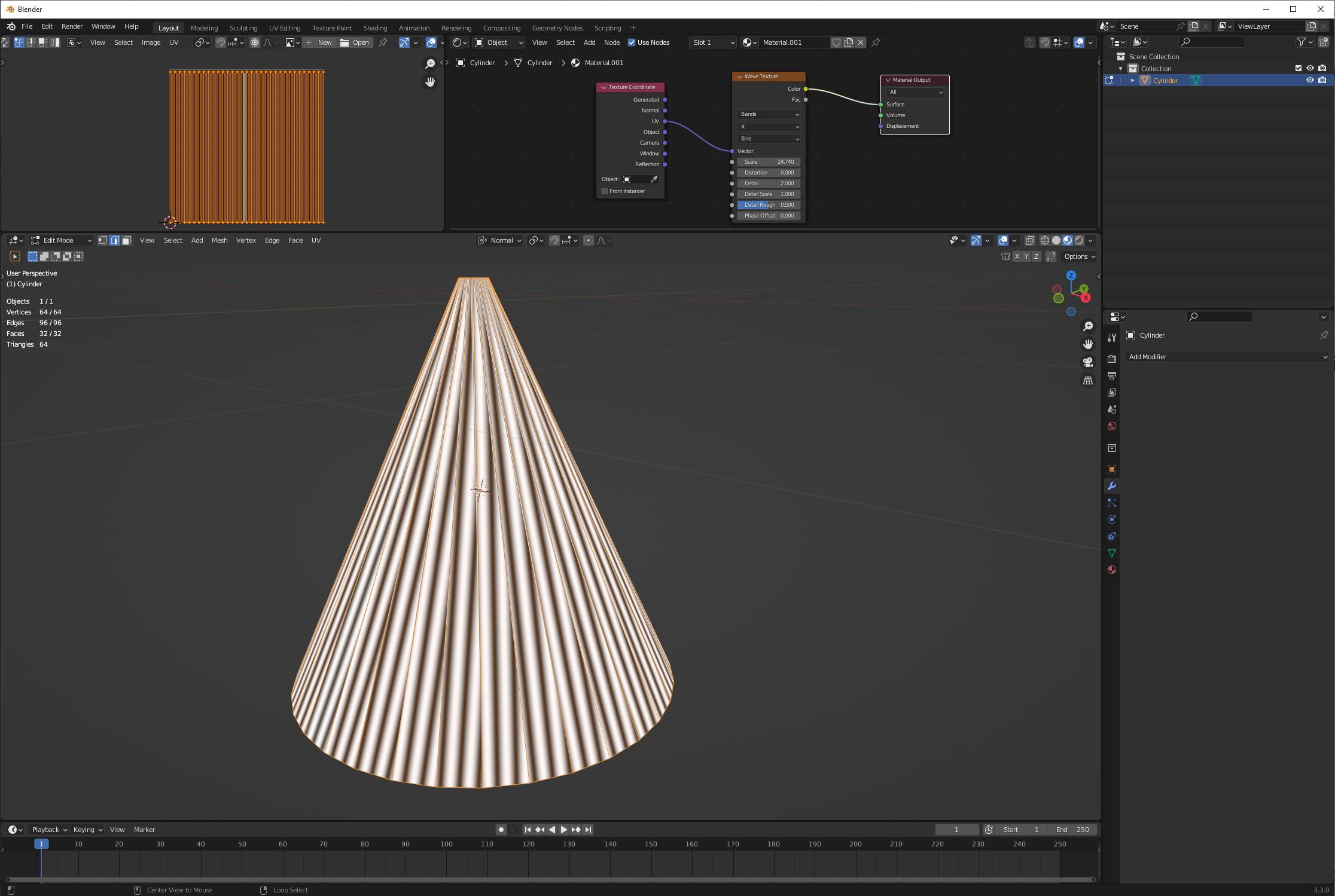
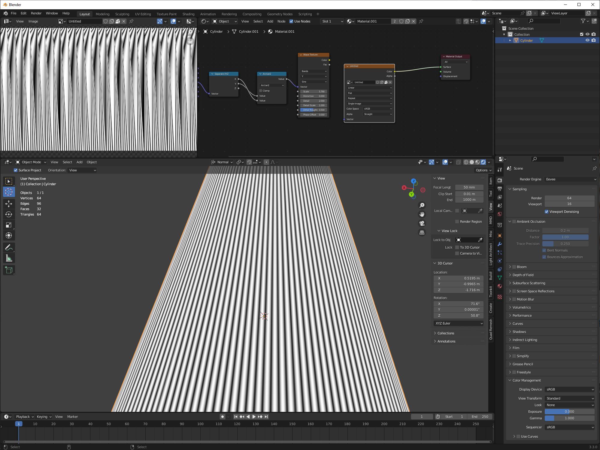
These are triangulation artifacts in the presence of distorted UV. We can show the same thing occurring on distorted UV without the use of any UV projection:

enter image description here

We can see that the (implicit) triangulation skews our wave texture to one side in the middle of each face. If we were to triangulate in the opposite way (perhaps with fixed alternate triangulate modifier) the skew would flip.

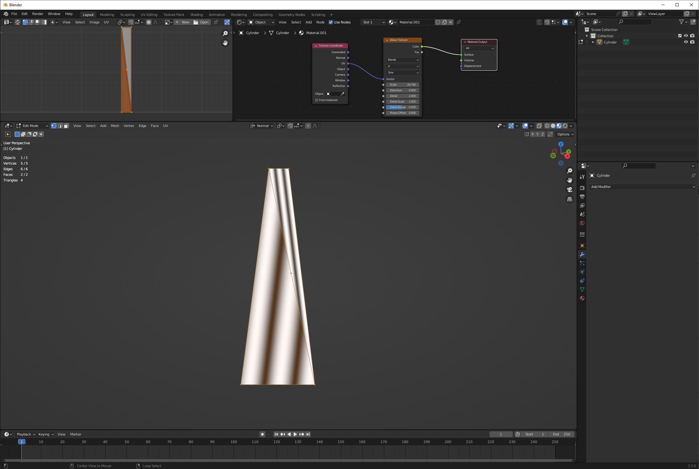
If we triangulate manually and look at a face like this more closely, we can see why:

enter image description here

I've triangulated the quad, then subdivided that line of triangulation. This is the center of the UV (as seen on the UV map as well.) Yet, because the face is a trapezoid, this point does not correspond to the center of the face. Our triangulation leaves us with two faces of uneven sizes in our world, but even sizes in our UV.

The same thing happens (in reverse, kinda) when we use a UV project with perspective. Now, we're mapping square faces to trapezoidal UV faces. Now the line of triangulation creates evenly sized world faces, but unevenly sized UV faces. Again, the actual center of the face does not correspond to the center of the UV.

So then, why does subdivision help this problem? Because we subdivide before triangulation, so each time we subdivide, the deviation of UV center from face center grows smaller:

enter image description here

So what are the solutions to this problem? The first solution is, don't use distorted UV. This is exactly why people try to minimize UV distortion. And the second solution is, just use a ton of subdivision levels to minimize the problem.

But there's a third solution, which is to bake the distortion into the image used by that UV:

enter image description here

Here, we can see that I made a texture using different coordinates (object polar coords) and when I bake it, that earlier distortion just goes away-- but it didn't go away entirely, it just got baked into the image texture instead. (This will also occur with texture painting; drawing a straight line on this mesh will give me a wiggly line of the 2D image.)

So one relatively straightforward solution here is to bake the texture from a heavily subdivided copy, to both minimize the number of verts and to minimize the size of triangulation artifacts.

$\endgroup$

You must log in to answer this question.

Not the answer you're looking for? Browse other questions tagged .