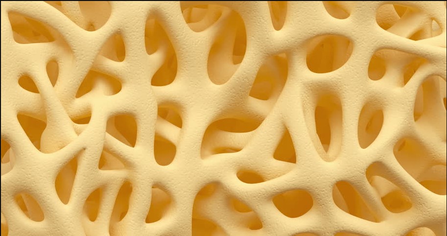
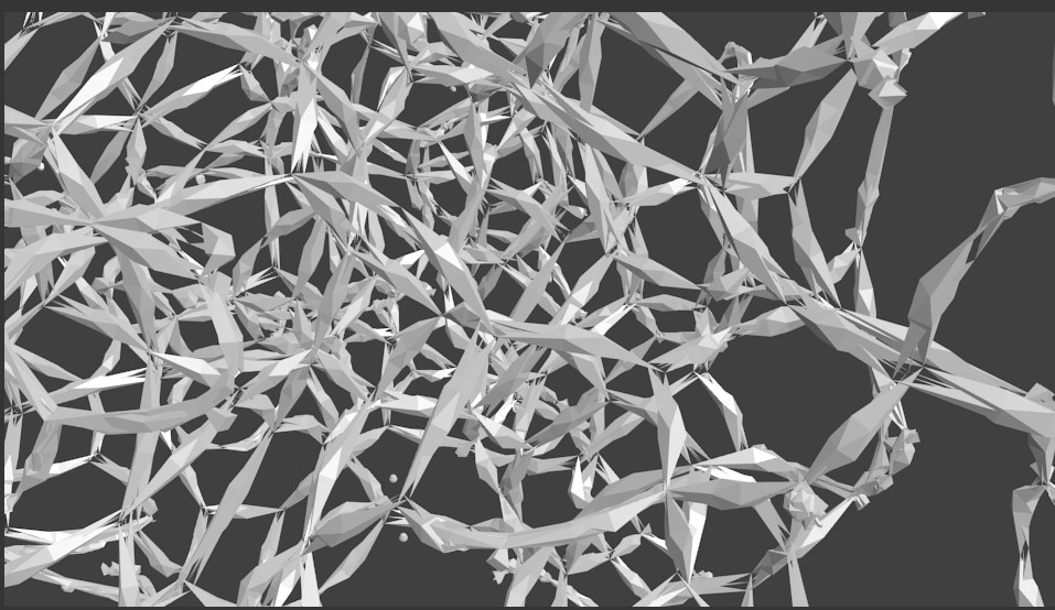
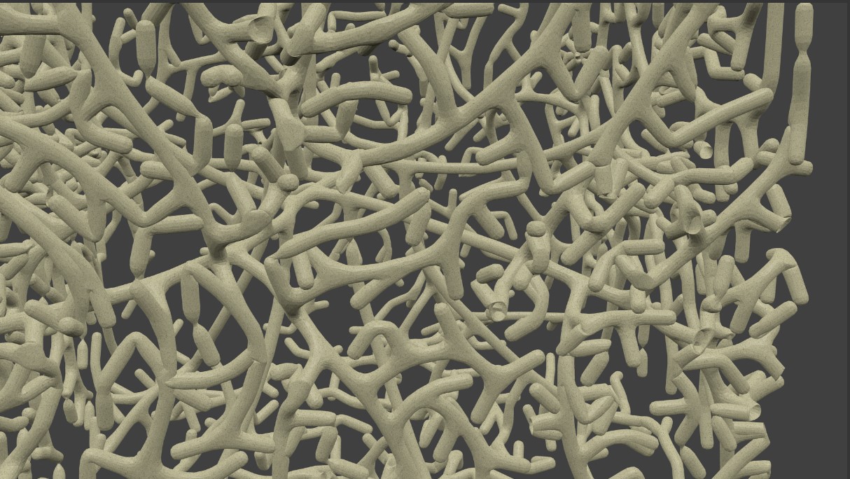
You can create similar results using a procedural volumetric material similar how you would render smoke but with a much higher density to simulate a solid diffuse surface.
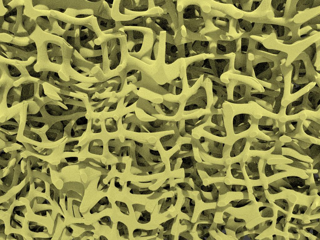
To create this, start with a mesh to act as a 'domain' for the volumetrics (eg, a Cube) and create a 'standard' volumetric Absorbtion/Scatter material node set up with a high density.
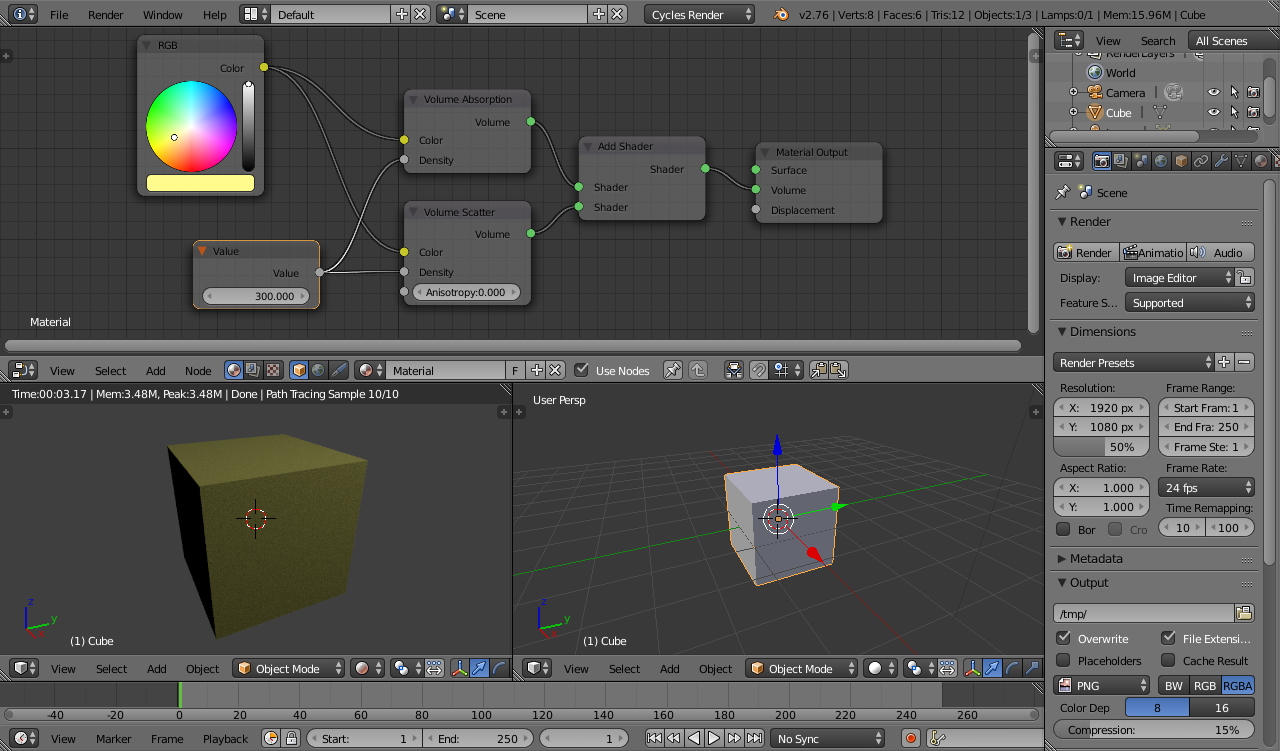
To demonstrate generating a volumetric surface within the domain volume you could start by using the Dot Product of the Object coordinates to control the density based on the distance from the origin to produce a sphere. To improve the quality of the rendered surface you may need to reduce the Step Size in the Volume Sampling properties panel - smaller values will produce a smoother surface but will increase render times.
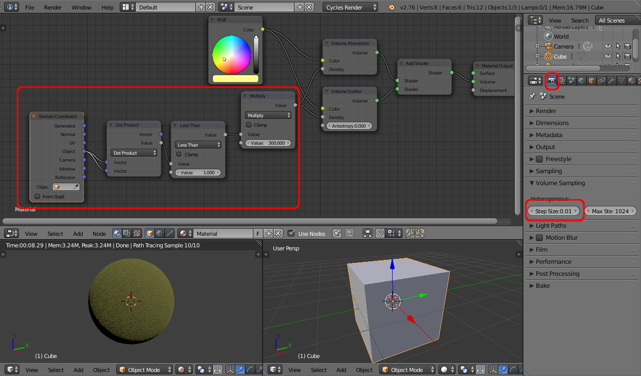
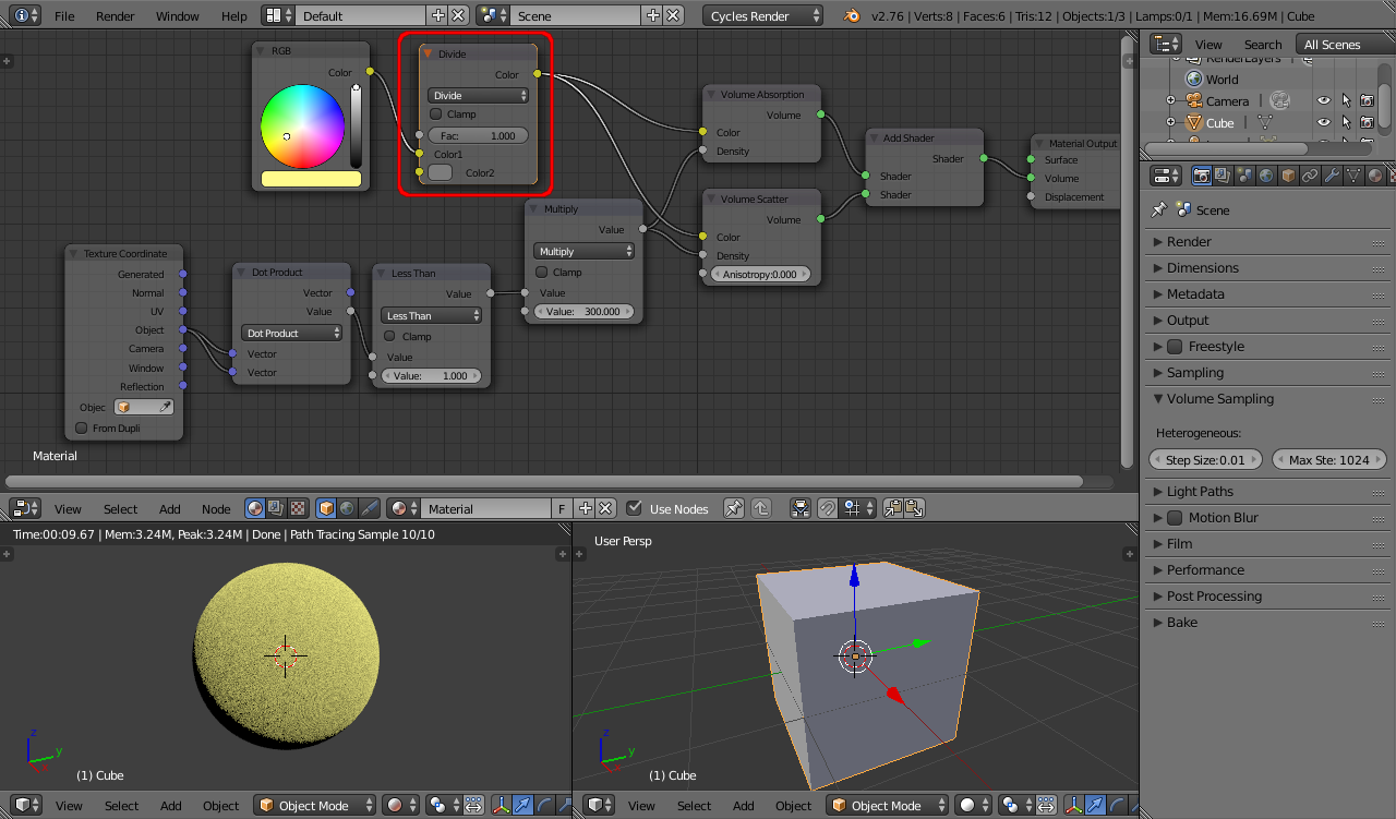
The volumetric material absorbs a proportion of the incident light resulting in a darker surface than you would expect with a Diffuse shader. To correct for this, inclulde a MixRGB node set to Divide to divide each channed by 0.2 to effectively "multiply up" the brightness of the surface by a factor of 5. This adjusts for the light lost by the Absorbtion/Scatter.
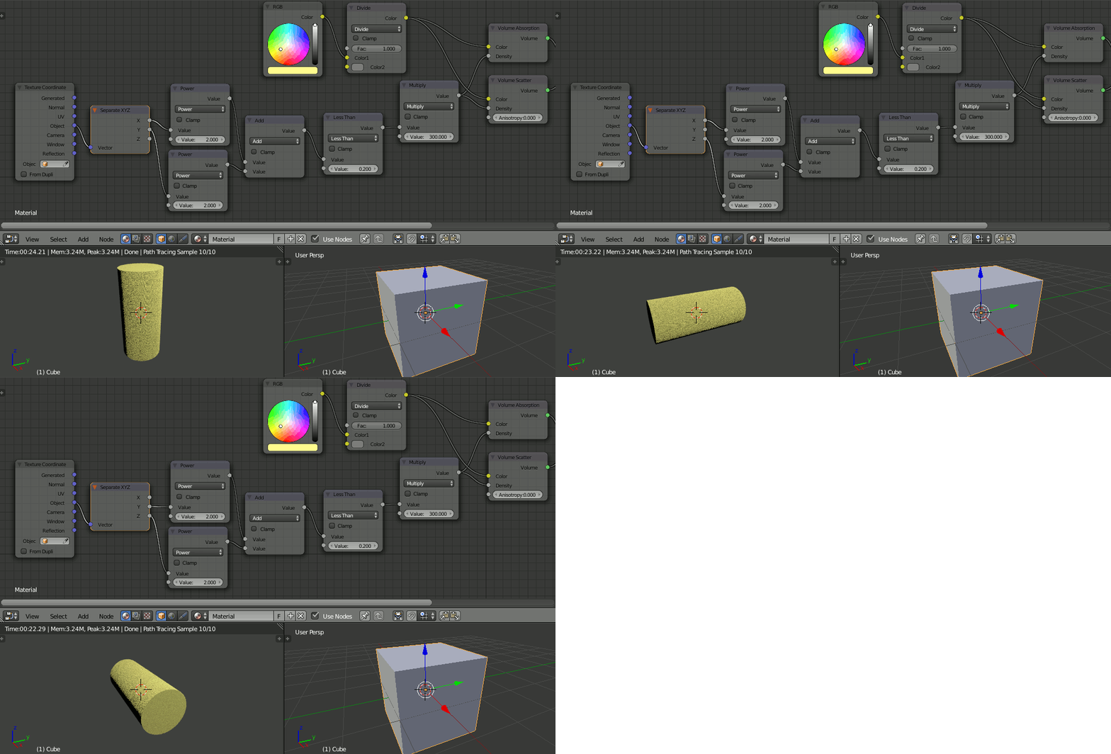
To create a cylinder, calculate the distance based on any two of the X,Y,Z channels - X and Y for a cylinder along the Z direction, Y and Z for a cylinder along the X direction, X and Z for a cylinder along the Y direction - using Pythagorus theorum a^2 + b^2 = c^2 .
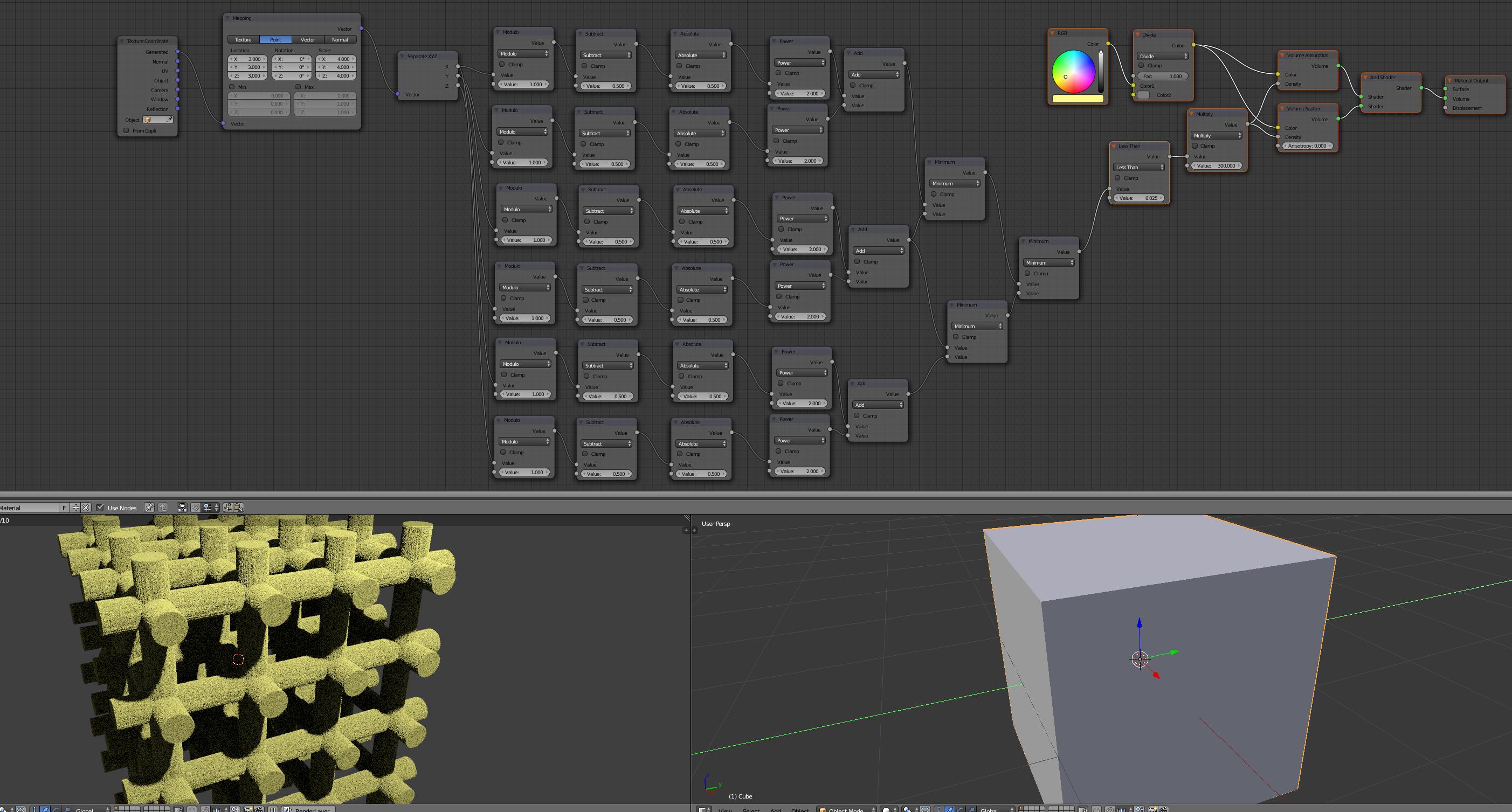
For an array of cylinders use Modulo Maths nodes to generate distances from a series of centrelines. For example, for lines spaced at 1 unit apart the distance from any line (placed on each integer x coordinate) can be calculated as :
distx = abs(mod(x, 1)-0.5)

Apply this to the coordinates of the two dimensions used to generate the cylinder, repeat for each 'direction' of the grid and use Generated coordinated and a mapping node to allow the number of cylinders in the grid to be easily controlled via the Mapping 'Scale' :
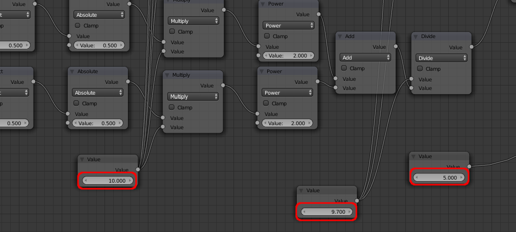
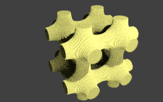
Using additional Maths nodes to combine the three arrays of cylinders allow the intersections to be blended into each other by allowing each cylinder to influence the surface by proximity. Here they are combined using the reciprical of the square ("1/(dist^2)") so that the closest line has the greatest effect with the influence falling off as the distance to the neighbouring lines increases. Adjusting the factors for the Multiply, Divide, Greater Than varies the width of the branches and amount of 'blending' between the cylinders to get the desired result,
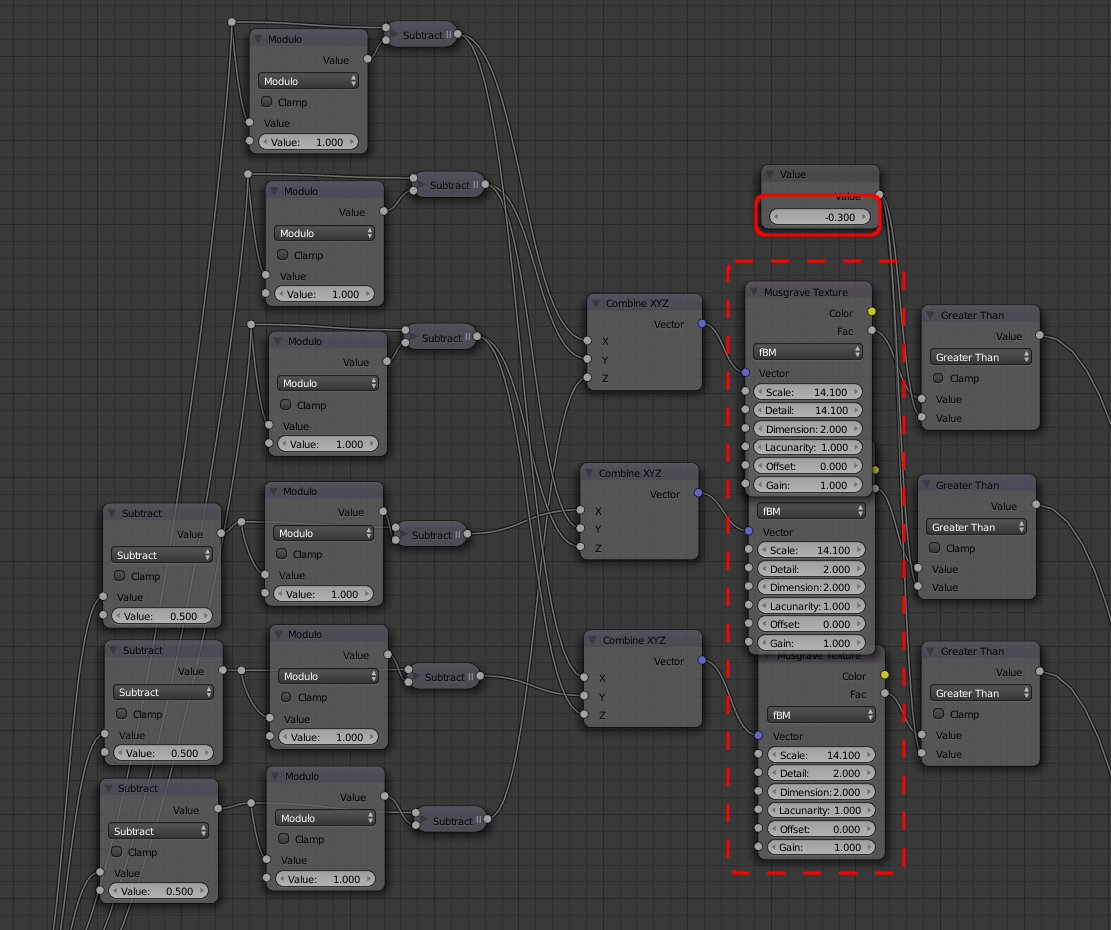
To add some variation we can use a Texture to affect the presence of each 'branch'. Care needs to be taken to calculate a 'coordinate' of each branch by 'truncating' each coordinate using Modulo functions (eg, to truncate x down to the nearest 1.0 use 'x - modulo(x,1.0) - this can then be passed to the texture so as to affect the entire length of that branch :
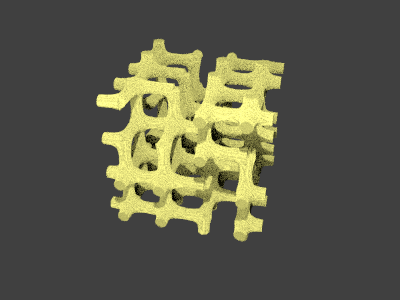
Finally, add some distortion by manipulating the original coordinates - in this case with a Noise texture (see full material below).
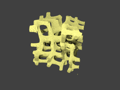
Bring it all together to create the following material :
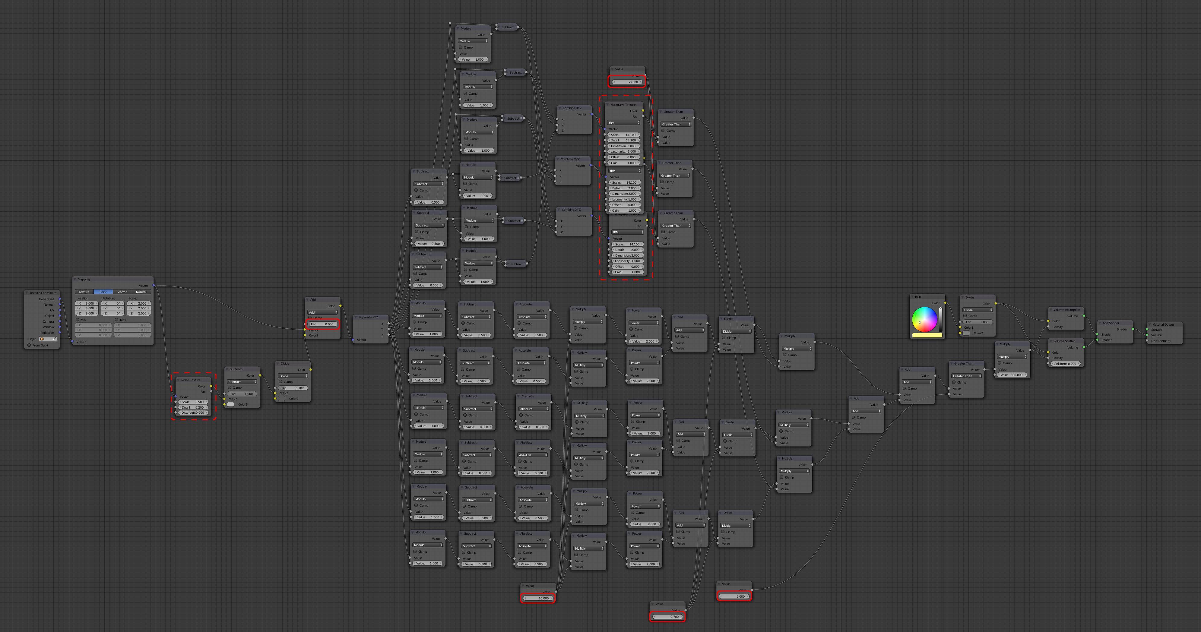
Adjust the highlighted nodes to adjust the line thickness, pruning of branches, and distortion.
Blend file attached 
Note : Care needs to be taken with the setting of the Volume Sampling settings (renamed to a 'Geometry' panel in newer versions of Blender). The Step Size indicates how far a ray should travel through a volume (in World coordinates) before being re-evaluated. Larger values will produce a faster render but sacrifice quality, while smaller values will produce more accurate results but will take considerably longer to render. The Max Steps parameter determines how many such 'steps' can be taken through a volume. For a 'see-through' volume (ie, where the branches are quite thin so light can travel right through the volume) you should set this to a value high enough so that the Step Size multiplied by the Max Steps is at least as large as the size of the Domain mesh - otherwise generated volumetric geometry may be clipped. If, however, the branches are thick enough to ensure there typically isn't a visible path through the domain, you may be able to set the Max Steps smaller without causing issues as rays would not be able to pass so far through the domain. The image at the top of the answer was rendered using Step Size of 0.002 with 1024 Max Steps.
Also note that Volumetrics are not normally affected by the 'World' illumination unless you enable Multiple Importance Sampling on the World - see Volumetric Scatter ignoring World lighting

