1
$\begingroup$

I made a cylinder (1): Shading = Smooth Mesh Tab: Normals = Auto Smooth

Then I cut the cylinder to get a quarter. (2 - 5).

I duplicated the quarter and rotated it 90 degrees (6). Now the shading looks bad. Someone has an idea how can I make it look like in (1)?

I don't want to connect the vertices, because I want it modular.

Shading problem after object cut

$\endgroup$
4

3 Answers 3

3
$\begingroup$

Smooth shading calculates the normal of any point in a polygonal face of a mesh by interpolating between the normals at its corners. The normals at the corners of a face are stored in the mesh data, and are usually calculated from the normals of adjacent faces.

When the cylinder is cut, some of the adjacent faces are missing, so the calculated corner normals are changed.

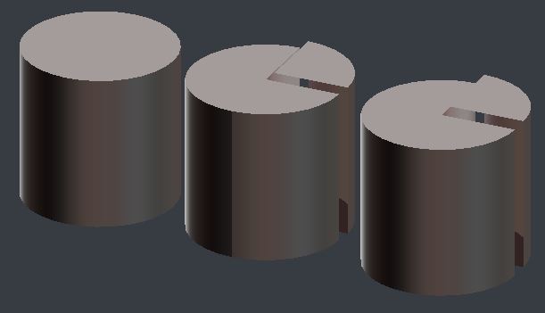
However, you can copy the corner normals from an intact cylinder to the cut cylinder by applying a Data Transfer modifier.

  1. Place the cut cylinder directly over an intact version of the same cylinder
  2. Add a Data Transfer modifier to the cut cylinder, with the option 'Face Corner Data' checked, set to copy from 'Nearest Corner .. etc', and the intact cylinder as its target.
  3. Apply the modifier

enter image description here

Cylinders: 1. Intact. 2. Cut with no transfer. 3. Cut with transfer.

$\endgroup$
0
$\begingroup$

For me, it looks like the normals of the both pieces shows in diffrent directions. Select one piece, go into edit mode and click on the menu point "Mesh". Under "Normals", go on "Flip Normals". Now, all normals shows in the same direction and the problem should de solved. Another problem could be, that you already applied a material on one piece, but you didn't mentioned anything like that in your description. Normally the normals are responsible for that kind of shading problem in the view port.

$\endgroup$
2
  • $\begingroup$ It's not working with flip normals. No, I didn't used any material. $\endgroup$
    – Johnny
    Commented May 5, 2017 at 22:16
  • $\begingroup$ That indeed is caused by normals orientation but flipping / recalculating them won't solve it at all. Orientation of normals shown on OP's screenshot technically is consistent, i.e. outside, but it is slightly mismatching which will provide shading artifact $\endgroup$
    – Mr Zak
    Commented Jan 27, 2018 at 17:11
0
$\begingroup$

After the duplication, there are multiple disconnected pieces of geometry. In case of multiple objects, merge them in object mode with ⎈ CtrlJ.

Then, in Edit Mode, join the meshes by selecting all vertices and merging them with W > Remove Doubles.

$\endgroup$

You must log in to answer this question.

Not the answer you're looking for? Browse other questions tagged .