2
$\begingroup$

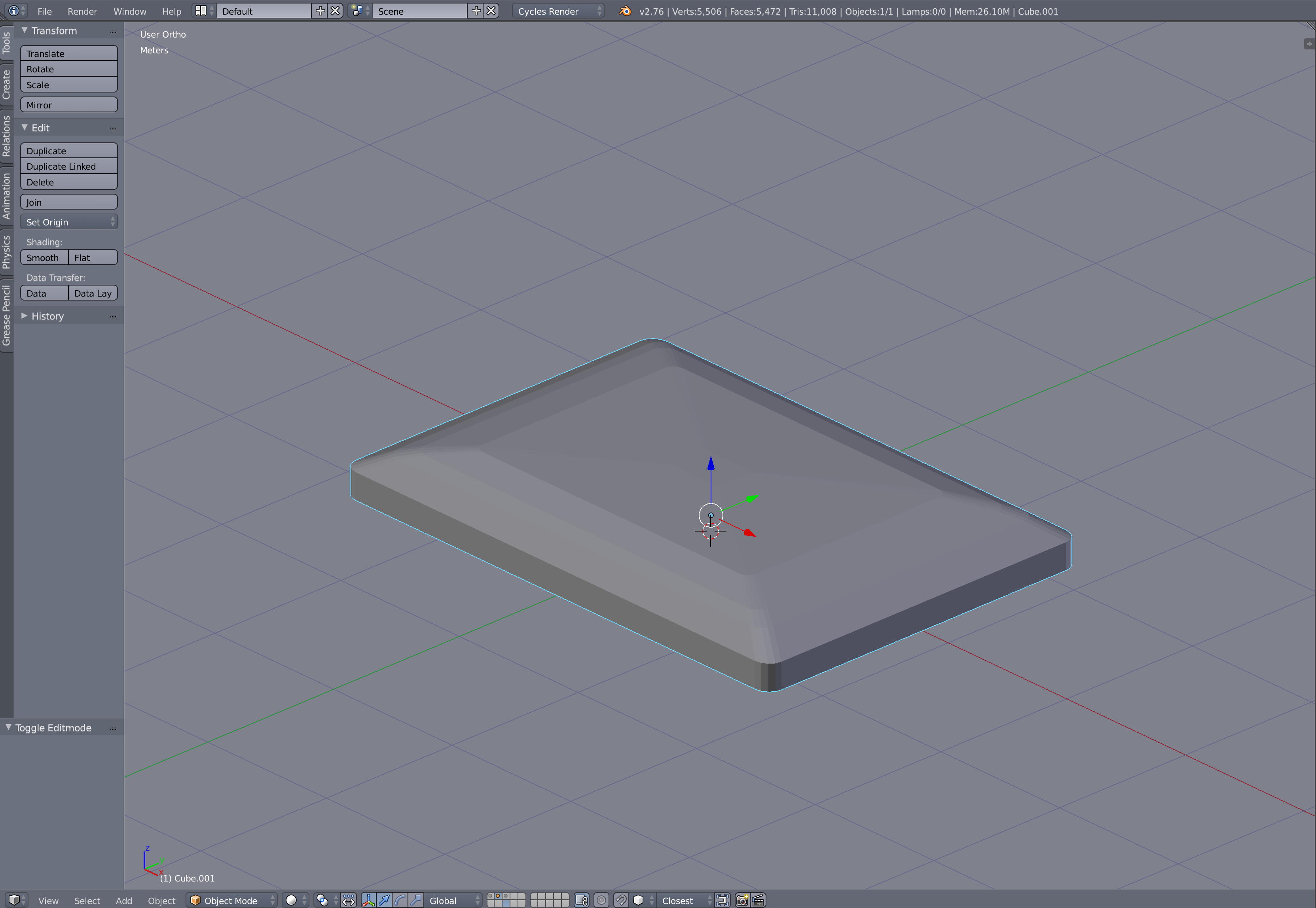
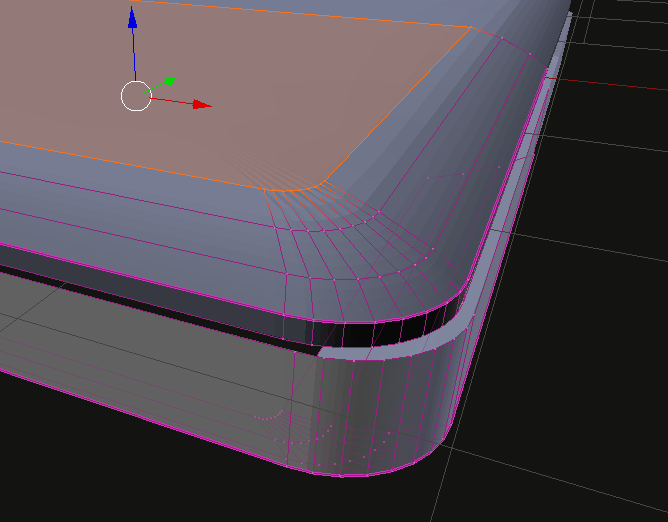
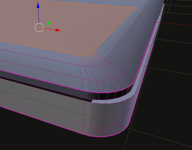
Ok, so I am modelling a surface for a mac book pro, and I realized that it looks kind of "unrealistic". It seems to me, that apple used some trick to achieve that surface. It seems like a smooth rounded surface inside a rectangle form...

I tried to achieve this with extruding and model according to a background pic but that didn't do the trick.

enter image description here

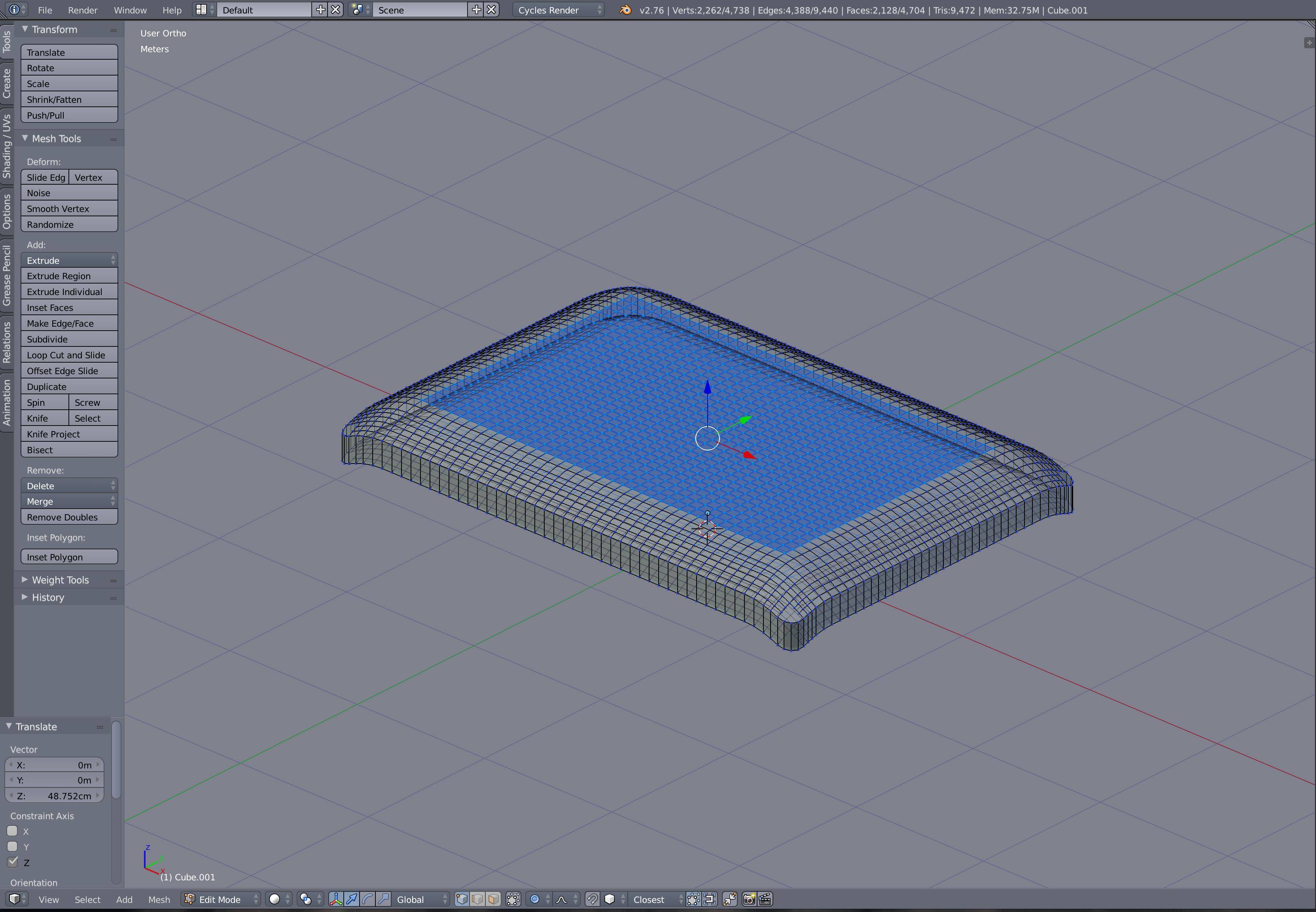
What I felt like would be the closest to the original was to go into proportional editing and just pull a certain amount of vertices out. But that looked like as seen in the pictures.

enter image description here

Maybe someone can give me a hint if I am doing something wrong. I want to have the "frame" sticked to the grid and then just have the rest of the vertices to move and form the smooth surface...

U can see in the pictures what I did and what I want to have but smoother... Maybe u get an idea

Thanks for your help.

Greetz

$\endgroup$
3
  • $\begingroup$ What you need is the bevel tool (Ctrl + B). Have a look at this answer for an example on how to use it: blender.stackexchange.com/questions/13919/… $\endgroup$
    – TLousky
    Commented Dec 21, 2015 at 21:12
  • $\begingroup$ If I understand correct, this may be a reference, and it means you should smoothen that sharp edge you have between top and middle part of the mesh. You can use several tricks for that, Bevel as said TLousky is one of them. $\endgroup$
    – Mr Zak
    Commented Dec 21, 2015 at 21:16
  • $\begingroup$ Hmm, no its not quiet what I mean... Because I already have it that way. I used the bevel option on the frame to get the round edges for the outer shape. The problem is, that I need round edges on the frame AND on the top. That picture is a good reference. $\endgroup$ Commented Dec 21, 2015 at 23:09

2 Answers 2

1
$\begingroup$

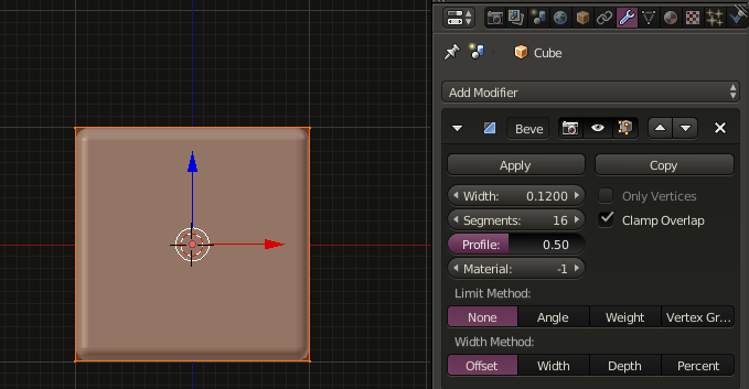
You could use the bevel modifier to create the rounded edges on the unscaled standard cube.

enter image description here

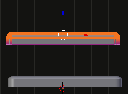
Add an edge loop Alt-R in the upper part and delete the bottom vertices.

enter image description here

Select the beveled part and scale it along the z-axis S,Z Note that you shouldn't scale the object to align it to the original model because this would distort the edges. Use select and grab instead.

enter image description here

$\endgroup$
2
  • $\begingroup$ Thank you, but you see the problem is that the basic shape is a rectangle not a cube or a square. So when I create a rectangle the bevel mod uses the rectangle shape (of course it dies) and therefore the corners have a higher X than Y. The exact dimensions are : 35,89cm and 24,71 cm. Now to achieve square edges I already had to use a plane and add loop cuts 1 cm from each corner vertex on the x and y axis. And the bevel doesn't even work on a rectangle with ctrl + B rounded edges... $\endgroup$ Commented Dec 25, 2015 at 10:03
  • $\begingroup$ @SebastianJaeger You would need to have the bevel with 2 independend radius values (which is not supported), what I described was a work around. This requires to start with something square and manipulate by scaling, align the model later to the required dimensions. $\endgroup$
    – stacker
    Commented Dec 25, 2015 at 10:20
1
$\begingroup$

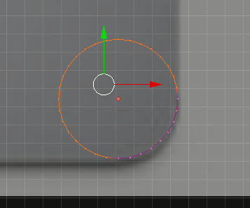
Another way would be to start with a circle remove all vertices but the ones required for a corner.

enter image description here

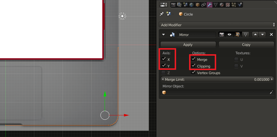
Add a mirror modifier and tick the highlighted options: enter image description here

Place the 3D cursor Shift-S Cursor to center In object mode set the objects center to the 3D cursor.

In vertex select mode extrude E the vertices to that the mirrored pieces connect.

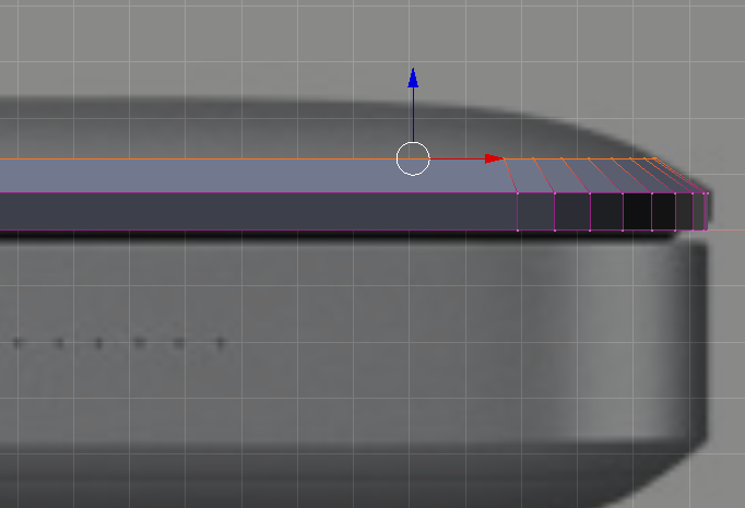
In front view select all and extrude along z-axis E,Z. and scale constrained to x,y: S, Shift-Z. repeat this.

enter image description here

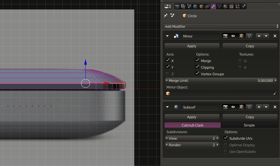
Add a subsurf modifier:

enter image description here

Select the sharp corner Alt-RMB and increase edge crease Shift-E.

Result after closing the top:

enter image description here enter image description here

$\endgroup$

You must log in to answer this question.

Not the answer you're looking for? Browse other questions tagged .