I was wanting to create an array of circles based on the vertices of a subdivide plane that could then have the rotation of say X be driven by a 2d B@W bitmap animation. Is there a way to achieve this if the plane had a uv map with the bitmap animation as a texture. I did see an example that used weight paint to drive position but that is not quite what I need. I'm very new to AN so apologies and thanks in advance for any help.
1 Answer
Welcome to Stackexchange! The first thing to do is to sample the values of the pixels of the image. This can be done using this small snippet of python code:
bpy.data.images[imageName].pixels[:][0::4]
We are basically making a copy of the pixel values and only getting every fourth pixel, the pixels list include the values of all four channels of the image since your image is BW, we only get one of the values, hence the [0::4].
Next, we get the width and height of the image, we get the width using:
bpy.data.images[imageName].size[0]
And the height using:
bpy.data.images[imageName].size[1]
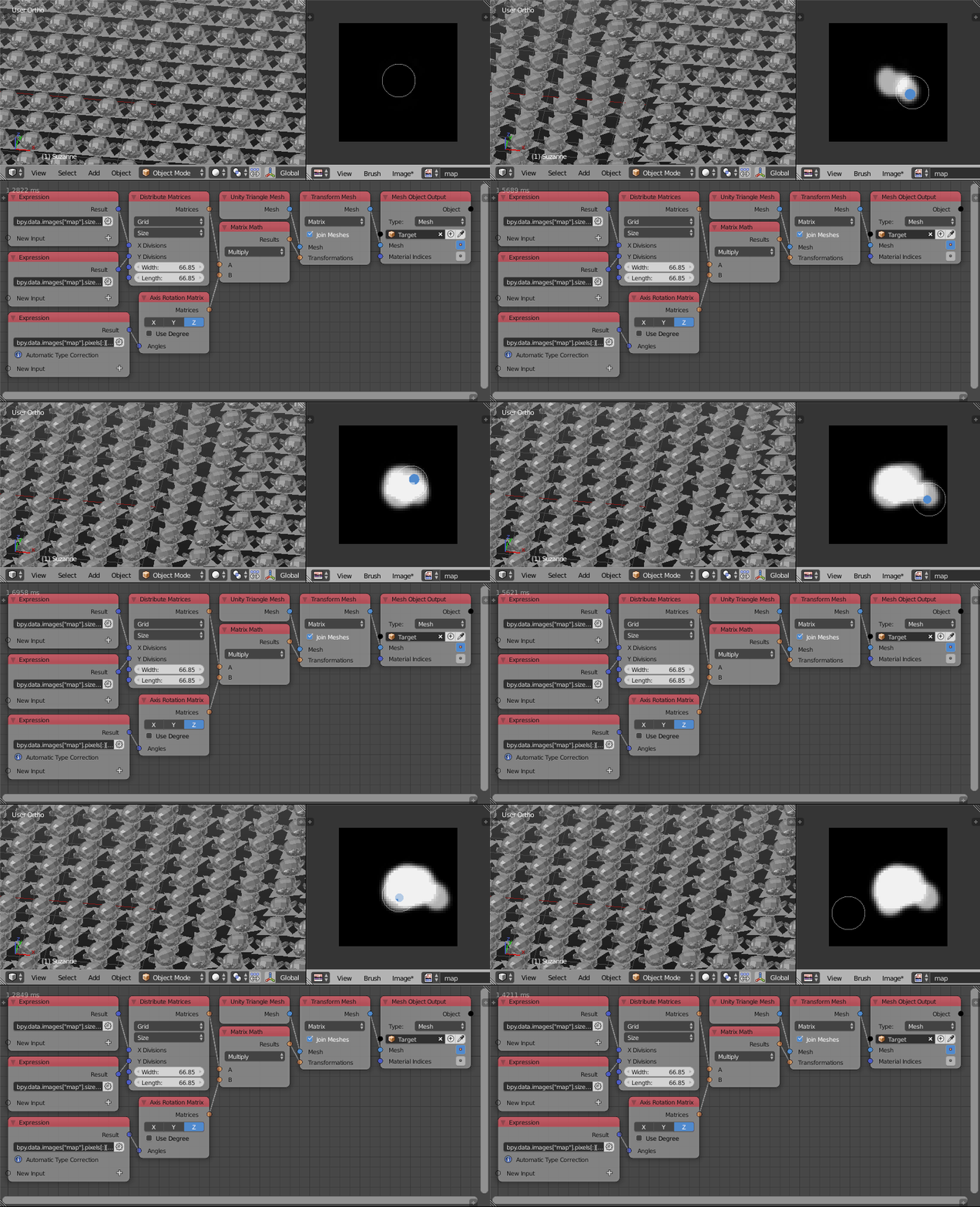
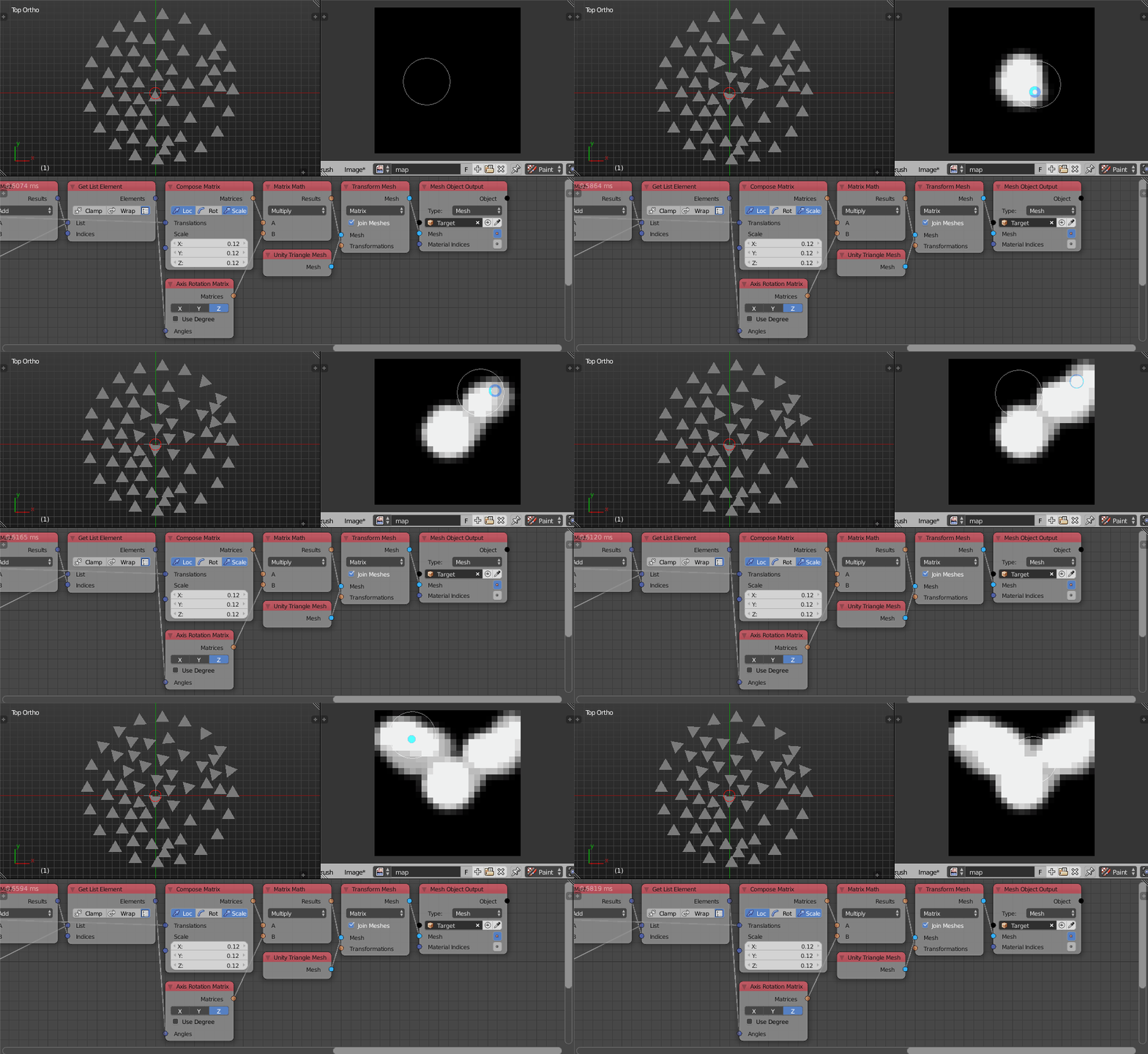
We then use the Distribute Matrices node to create the grid with the same width and height of the image. We use the Axis Rotation Matrix node to create a rotation matrix from the pixel values and multiply both matrices list. Depending on which version you are using, you will either use the Replicate Mesh node to replicate a unity triangle along the matrices or use the new Transform Mesh node to replicate the unity triangle as I will be using here. We then output that mesh and set the container object as the parent of your circle object and activate Face Duplication for the container object.
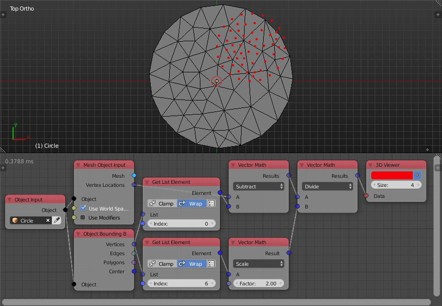
The pixels of an image have a grid structure, thus assigning the values of pixels to objects distributed on a grid is easy. If the objects are not distributed on a grid, then one would have to guess what the value of each object is, this is called an Interpolation. There are multiple types of interpolations, the simplest of which is called the Nearest Neighbour Interpolation, and this is what we will be using here. Basically the bounding plane of the structure is aligned with the image, then for each object, we find the closest pixel to it and assign its value to it.
Let the structure be defined by the vertices of a mesh. We imagine the image as a plane whose lower left corner is at $(0,0)$ and upper right corner at $(\text{Image Width},\text{Image Height})$. The first thing to do is normalize the vertices locations, that is, transform the vertices locations into the range $[0,1]$ in both axis:
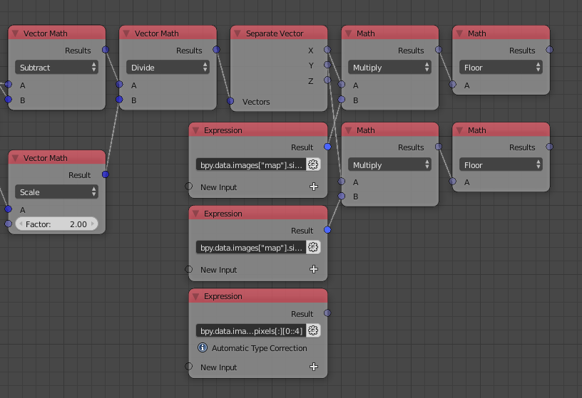
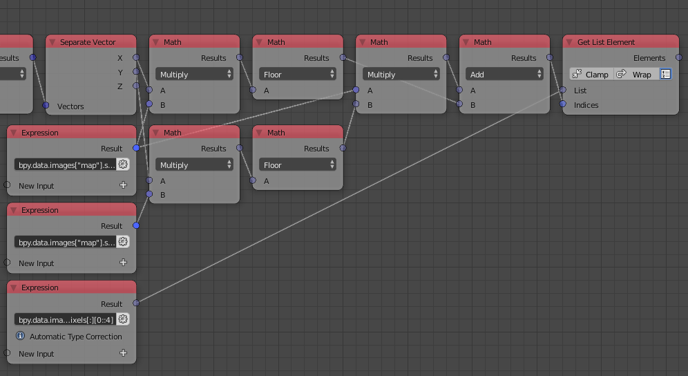
See the documentation for more info. Then we multiply the x location by the width of the image and the y location by the height of the image, that way, the bounding plane of the structure aligns with the image we imagined. By flooring the x and y locations we get an integer representing the index of the column and row of the closest pixel to each vertex:
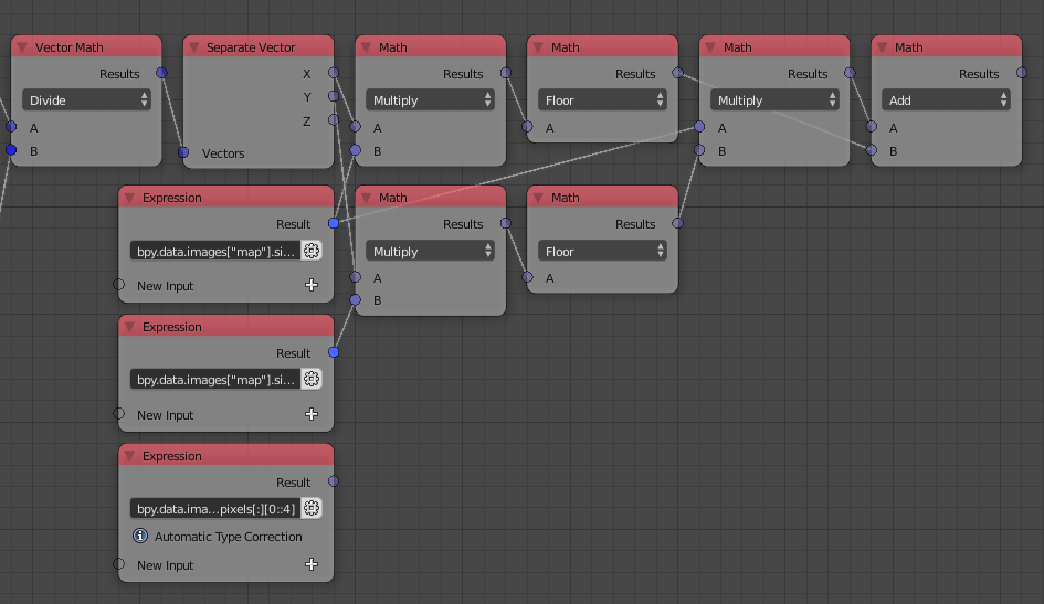
Linear Indexing can be used to compute the index of a pixel in a flat list knowing its column and row index, the equation is $\text{index} = iw+j$ where $i$ and $j$ are the indices of the rows and columns respectively and $w$ is the width of the image, by implementing that:
Now, all we have to do is sample the pixel values at those indices as follows:
Finally, compute the matrices and use them just as we did before:
Blend file for study:
-
$\begingroup$ Thanks for the fast response! I'm having a little trouble replicating the setup. I can't find a couple of the nodes you have used, these are: Unity Triangle Mesh and the Transform Mesh. Also I have not found Axis Rotation Matrix but instead used a Rotation Matrix. Not sure if that is the same. I'm also getting a "Wrong Output Type" from the expression 'bpy.data.images["Map"].pixels[:][0::4]' $\endgroup$ Commented Sep 18, 2018 at 16:50
-
$\begingroup$ @Bopstar What version are you using? I am guessing it is
2.0. If so, can you download a 2.1 build? For the wrong output type, can you click on the gear button and search for Float List, does that fixe the problem? $\endgroup$ Commented Sep 18, 2018 at 17:35 -
$\begingroup$ Thanks for taking the time to response Omar. Did manage to get 2.1 installed and working. Yes the "Float List" did the trick. But still can't get your setup to work for some reason. I'm getting a "different length" message under the Matrix Math node. Not sure what I have done or have missed. Thanks for your patience Omar. $\endgroup$ Commented Sep 19, 2018 at 6:10
-
$\begingroup$ Ok, all good now not sure what changed. However, not sure how to get the circle to attach as per you example with the monkey. $\endgroup$ Commented Sep 19, 2018 at 7:27
-
$\begingroup$ @Bopstar Can you see the triangles already? Blender can instance an object over the faces of a mesh, in this case, our triangles. Check the documentation here to see how it works. All you have to do is activate it and parent the object to the source object. $\endgroup$ Commented Sep 19, 2018 at 8:29

