14
$\begingroup$

I am currently trying to recreate the laser line described in Making a Laser in Cycles - Straight Beam of Light?

I have selected the Cycles Renderer, enabled nodes on my light (spot and point tested). I can modify the strength and color using various node outputs so the nodes seem enabled. I have tested the other types of laser schemes presented in the link above but none produce output close to what is expected.

Is it the light source which I should be modifying the nodes for?

Something that feels quite strange to me is the use of the value of the cross product which I am uncertain how it would be defined. (area of the parallelogram between the vectors?) Node scheme for line laser

Have I missed something fundamental about how nodes work and if so a source to start reading and learning about them would be appreciated.

Thanks in advance.

$\endgroup$

1 Answer 1

19
$\begingroup$

The use of the Cross Product in that example doesn't make much sense - in fact, I don't seem to be able to get that setup to work. The Value output of the Cross Product gives the average of the individual (X,Y,Z) elements of the vector. This could be argued to make sense if the X, Y, Z all have the same sign (ie, all positive or all negative) but as soon as you get a mix of different signs the result becomes effectively meaningless.

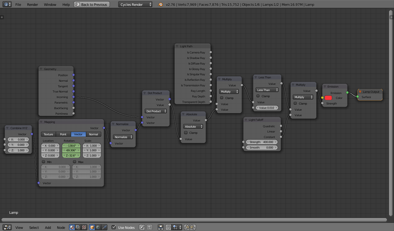
My own take on the 'Laser Line' issue would be to use a Point lamp with a small size (eg, 0.01) with the following nodes :

laser nodes

The 'Size' of the lamp will affect the width of the laser line, as will the value in the Less Than node.

Here a 'seed' vector is used to control the direction of the laser, adjustable via the Mapping node. This allows the vector to be easily rotated. The Dot Product compared the direction of the ray with the direction vector - if they are close enough (within the Less Than threshold) then the lamp emits light, otherwise it does not. The Ray Length is used to effectively tighten threshold the further the ray falls from the source - this ensures the ray doesn't 'spread' as it gets further from the source. Similarly, the Light Falloff node ensures the strength of the lamp remains constant regardless of distance.

This can produce the following result :

animated

$\endgroup$
1
  • $\begingroup$ Thank you for the detailed answer, and apologies for my quite late approved answer tick. I have since this posting made a few different approaches to laser line simulations optimizing against different parameters (speed, realism) I'll see if I can get them to a shareable platform some day and post here for future searchers. $\endgroup$
    – Tobyndax
    Commented Feb 6, 2020 at 15:04

You must log in to answer this question.

Not the answer you're looking for? Browse other questions tagged .