4
$\begingroup$

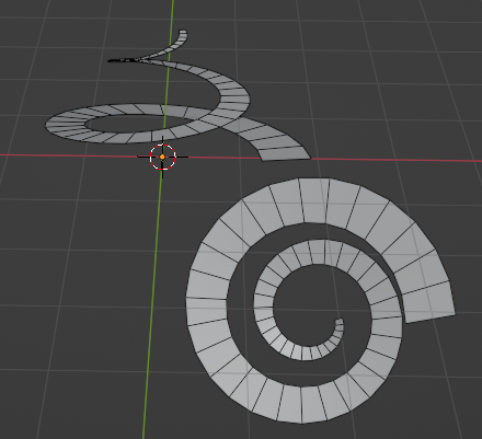
I am trying to create this flat spiral that will get narrower towards the top. I have managed to create it in several ways, but I cannot reproduce the same result using only modifiers.

I have tried using the Array modifier together with the screw modifier, but could not keep the parts merged when scaling (using an empty) also, I would like to create the spiral scaling without using the Lattice modifier. Would like to keep the spiral procedural, so I can edit it later if needed.

Any ideas?

.blend file https://easyupload.io/kac7a5 enter image description here

$\endgroup$
4
  • $\begingroup$ Why not using a lattice modifier ? it's as procedural as it can get $\endgroup$
    – Gorgious
    Commented Mar 1, 2022 at 15:42
  • $\begingroup$ Just because I feel there is a way to do it using only the array / screw modifiers. Using the lattice feels like the easy way $\endgroup$
    – Ebi
    Commented Mar 1, 2022 at 15:51
  • $\begingroup$ geometry nodes is a modifier too....allowed? $\endgroup$
    – Chris
    Commented Mar 1, 2022 at 16:00
  • $\begingroup$ haha :) of course, it will be nice to see unusual attempts $\endgroup$
    – Ebi
    Commented Mar 1, 2022 at 16:29

4 Answers 4

6
$\begingroup$

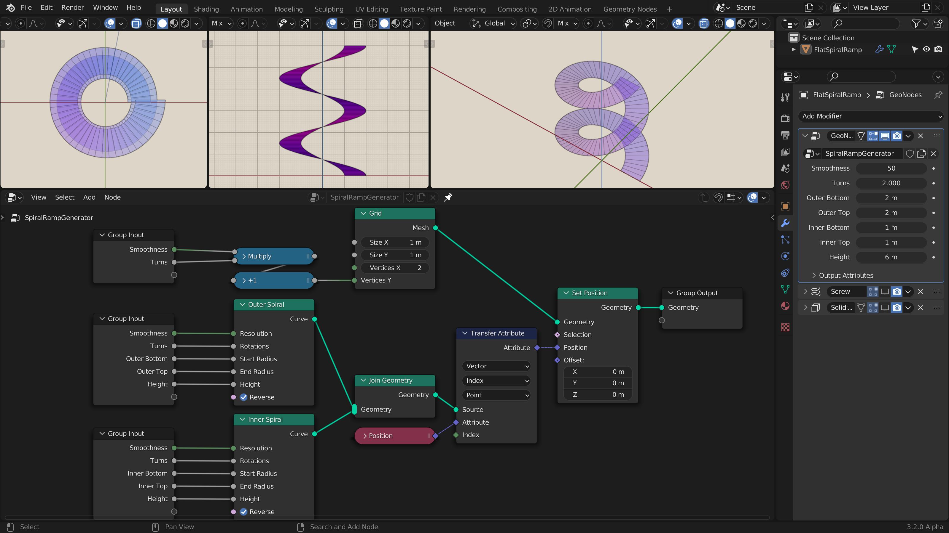
Here's another way of doing it in Geometry Nodes. It's a much simpler and better method than my first answer, with more precise control and none of the drawbacks—no tilting, perfectly flat ramp ends, more fine-grained rotation control etc. Here's the node setup:

enter image description here

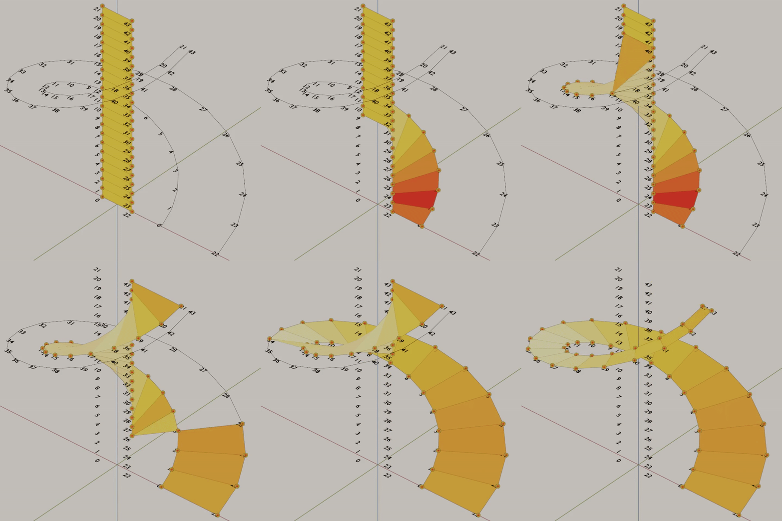
How it's done: create two Spirals (one for both sides) and a single-column Grid with the same amount of vertices with the two spirals. Then, move (Set Position) the vertices of the grid unto the spirals, matching the vertices on the left side of the grid with one spiral, and the vertices on the other side with the other spiral, using their indices. That's it.

$\endgroup$
11
  • 1
    $\begingroup$ @Ebi You didn't say which part you're having trouble with, and I don't know your level of familiarity with GeoNodes, so I guess I'm gonna go through it all and ELI5: First you have the two Spirals, outer and inner, with all their settings exposed in the Group Input(s) so you can tweak them from the modifier UI (group inputs are duplicated just for convenience and readability, the values are the same as long as they're linked to the same-named sockets). Now we need to "stitch" these two spirals together with edges and faces in between their corresponding points. $\endgroup$
    – Kuboå
    Commented Mar 7, 2022 at 23:22
  • 1
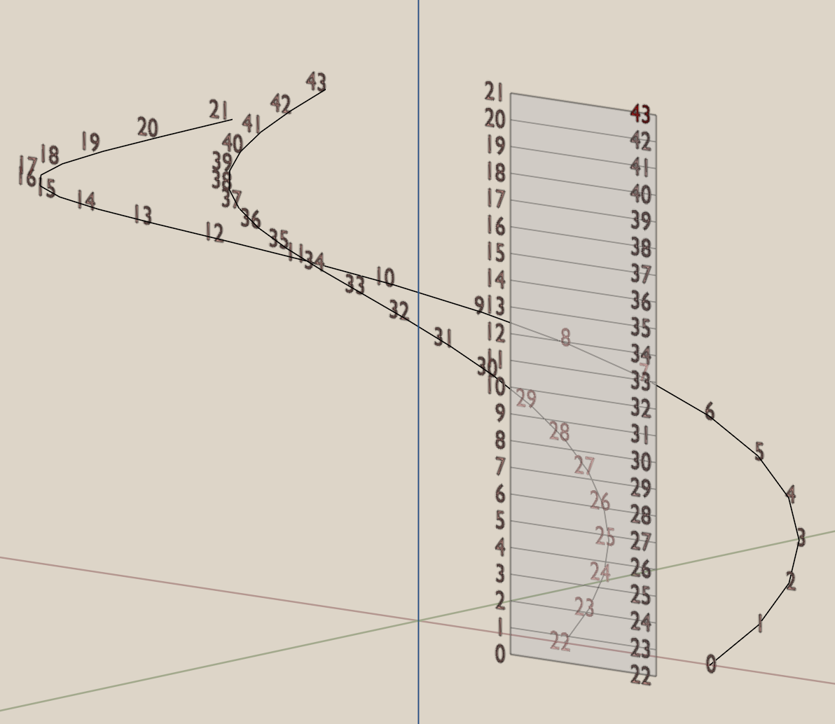
    $\begingroup$ To do that, I'm using a single-column Grid, and simply moving its points onto the spirals, using their index numbers: first point of Grid (Index0) is moved to where the first point of Spiral (Index0) is, second grid point (Index1) to second spiral point (Index1) and so on, like this: i.imgur.com/WxXKssE.mp4 To do this, we have to have the same amount of vertices total in the grid and the spirals. Smoothness*Turns determine the amount of vertices spirals have already; to match that, I have to multiply them manually (and add +1) and feed into the Grid myself. $\endgroup$
    – Kuboå
    Commented Mar 7, 2022 at 23:22
  • 1
    $\begingroup$ I "join" the spirals together because: let's say I have a Grid of 44 vertices; their vertex index numbers would go from 0 to 43, but since I have two spirals, I'd have two lists that go from 0 to 21 and it wouldn't know which Spiral Index0 points to move the Grid Index0 to. Joining them makes them a single block so their index numbers go from 0 to 43 just like the Grid's. Then, I simply tell it to take (Transfer Attribute) the Spiral's Position information (which is a Vector), according to their Index, and use that to move (Set Position) the Grid's points. $\endgroup$
    – Kuboå
    Commented Mar 7, 2022 at 23:22
  • 1
    $\begingroup$ @Ebi Ah, I see. In normal modeling, in Edit Mode, we could simply use tools like Bridge Edge Loops or Fill to create the faces between the spirals but since we don't have those in GN (afaik), the grid simply acts as a ready-made source of faces. $\endgroup$
    – Kuboå
    Commented Mar 8, 2022 at 9:47
  • 1
    $\begingroup$ @Chris Thanks. It seems pasteall site has come to an end, it wasn't obvious back then if that or blend-exchange would survive longer :) It's a very simple setup to replicate, but updated the answer with a new link anyways. $\endgroup$
    – Kuboå
    Commented Dec 5, 2022 at 14:16
5
$\begingroup$

Here's my Geometry Nodes entry, with full parametric controls:
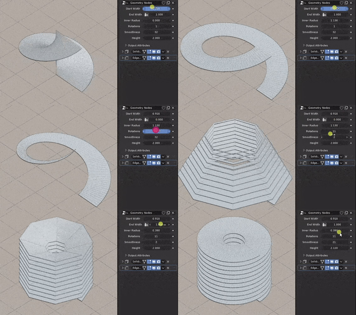
enter image description here

It's basically the Spiral curve primitive with a Curve Line as profile so you get a ramp. There are three challenges:

  1. As soon as you play with its parameters, like height, or rotation amount, the curve gets tilted
  2. It needs to (be able to) get smaller towards the top
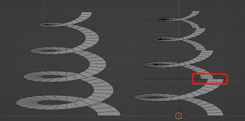
  3. It's not flat at ramp endings in top view

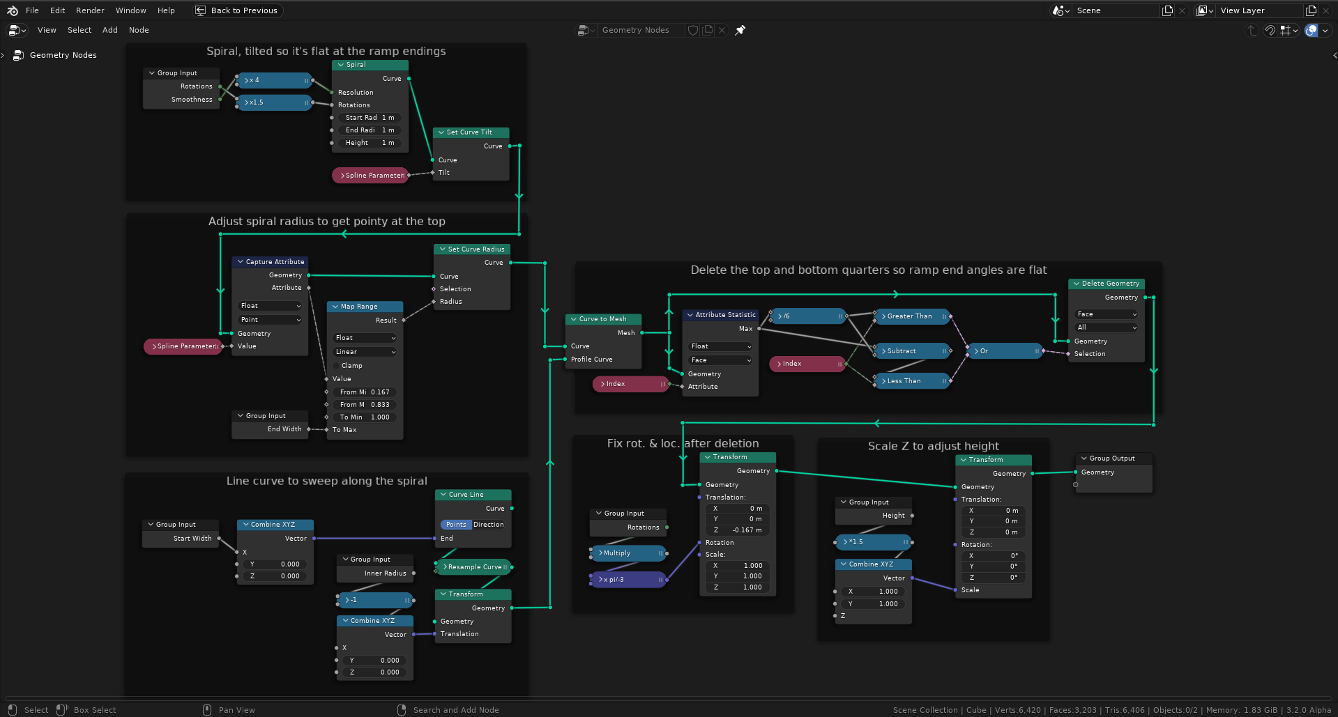
First two problems get under control with Spline Parameter. Third problem proved more troublesome, but I noticed that ramp ending lines get orthogonal every quarter as long as Resolution is a multiple of 4 and they are not open ended (since their angle gets averaged by both sides, if one side is open, it doesn't stay flat). So I ended up giving every rotation 6 quarters and trim the ones at both ends, leaving me with the middle ones with the orthogonal ends. 6 quarters mean every rotation in the result is actually 1.5 rotations in the source Spiral, that's why you see those two numbers at the very beginning, tied to Rotations and Smoothness. The Spline Parameter value going into Set Curve Radius is also mapped to a new range to compensate for this. Rest is more maintenance of transformations.
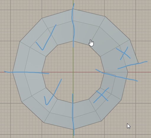
enter image description here

Here's the full node view:

enter image description here

And here's the file.

$\endgroup$
6
  • 1
    $\begingroup$ Very nice, and nice presentation, too. I like the way you have solved the tilt problem on the curve spiral. Is that just luck, or is there some logic to the relationship between the spline parameter, height and tilt? I notice, now, that in order for the tilt to be Z-up all the way, tilt must be set to spiral height * parameter, but have no idea why. $\endgroup$
    – Robin Betts
    Commented Mar 2, 2022 at 16:25
  • 1
    $\begingroup$ @RobinBetts Thanks! Tilt used to have bunch of calculation nodes attached to it, but never worked great. After I abandoned the idea of using the Spiral node's radius and height values and set them all to 1 so I could use Multiply freely where needed, I noticed that that fixed it anyways. So I think (not exactly sure) it's due to them all being 1. I calculate the height at the very end with Scale Z, and adjust the radii by moving the end point of the Curve Line. End edges are not actually perfectly flat and I had a whole network of nodes to fix that but then decided that it's not worth it. $\endgroup$
    – Kuboå
    Commented Mar 2, 2022 at 16:38
  • 1
    $\begingroup$ That is so slick! Love it! Thanks so much $\endgroup$
    – Ebi
    Commented Mar 2, 2022 at 19:19
  • $\begingroup$ Which blender version are you using? $\endgroup$
    – Ebi
    Commented Mar 3, 2022 at 9:38
  • $\begingroup$ @Ebi 3.2 Alpha. You can see it in the bottom right corner of the last screenshot. Why, are some of the nodes not available in yours? $\endgroup$
    – Kuboå
    Commented Mar 3, 2022 at 9:51
3
$\begingroup$

Here's a GN Group for it, giving pretty comprehensive parametric control:

enter image description here

It's mainly just an exposure of Curve Primitive > Spiral paramaters to the modifier interface, with the following notes:

  • The height is set 'manually' after the curve has been converted to a mesh, to avoid having to mess with automatic curve tilts.
  • The curve's Index is captured, and passed on to the mesh for use in setting the height, normalized. (It's divided by the curve's resolution)

enter image description here

Blender 3.0: https://pasteall.org/blend/67f1888f7749427f87b357d3e41ae07e

$\endgroup$
1
  • $\begingroup$ Thanks so much :) will test it tomorrow $\endgroup$
    – Ebi
    Commented Mar 2, 2022 at 22:08
2
$\begingroup$

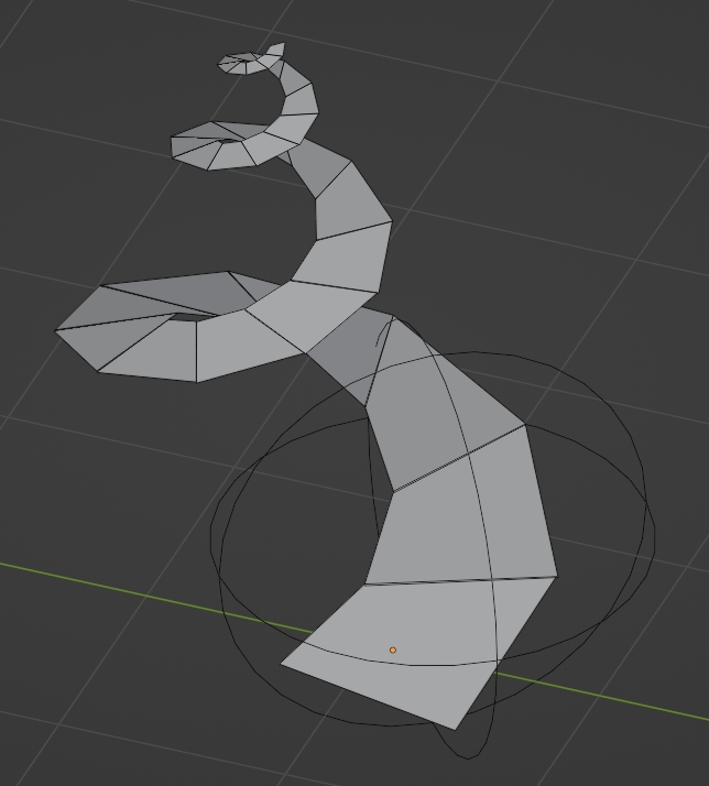
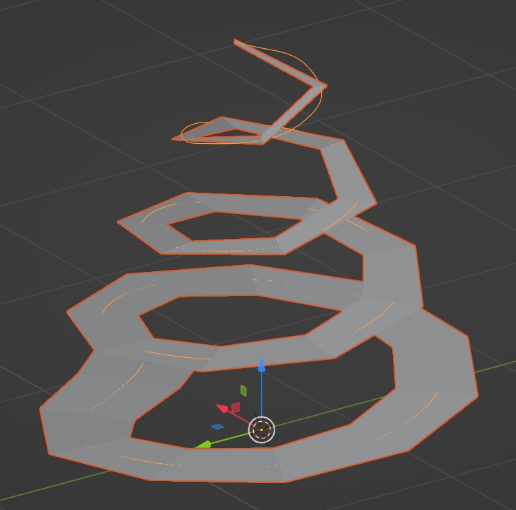
You can do it with an Array modifier with an empty as Object Offset, just move, rotate and scale the empty a bit, then you'll need to edit the mesh so that the instances stick to each other:

enter image description here

Another solution is an Array along a spirale curve (that you can create with the Add Curve: Extra Objects addon, then ShiftA > Curve > Curve Spirals > Archemedian, then tweak the parameters in the Operator box), and you gradually scale down the vertices radius of the curve from bottom to top:

enter image description here

$\endgroup$
5
  • $\begingroup$ not a very clean way of doing it $\endgroup$
    – Ebi
    Commented Mar 1, 2022 at 15:35
  • $\begingroup$ mmmmmh why that? $\endgroup$
    – moonboots
    Commented Mar 1, 2022 at 15:36
  • $\begingroup$ uv's are quite distorted, and the control goes to the mesh and not the modifiers $\endgroup$
    – Ebi
    Commented Mar 1, 2022 at 15:37
  • $\begingroup$ Your second solution is interesting! I will test it later on $\endgroup$
    – Ebi
    Commented Mar 1, 2022 at 20:20
  • $\begingroup$ don't use too many vertices in your curve, 4 per turn is enough, otherwise you'll have a lot of radius to set ;) $\endgroup$
    – moonboots
    Commented Mar 1, 2022 at 20:30

You must log in to answer this question.

Not the answer you're looking for? Browse other questions tagged .