3
$\begingroup$

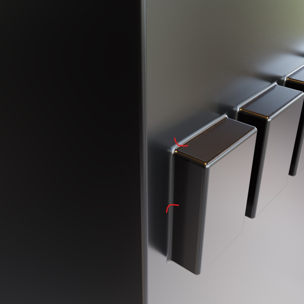
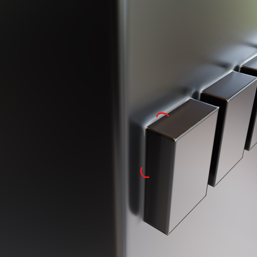
I've been trying to recreate Gesy Bekeyei's clever trick (scroll below to see what I'm referring to) in using a black and white gradient texture to influence the Bevel Shader's radius to create custom bevels for each differently sized segments of the object. I've achieved a good part of that, however, the parts of the segments that make contact with the surface curve inwards, instead of outwards, as it normally would if a Bevel Modifier was used. I believe my UV unwrapping could be the reason but after unwrapping in various ways, I still haven't achieved the desired look.

Any of you good folks mind helpin' me figure this out?

By the way, unrelated - hope y'all had a great Christmas! :)

This is the look I want enter image description here

This is what I'm getting enter image description here

$\endgroup$
5
  • $\begingroup$ If it's curving in the wrong direction, could it just be that you've UV unwrapped your object in the wrong direction on the gradient? $\endgroup$
    – stphnl329
    Commented Dec 27, 2019 at 15:52
  • 3
    $\begingroup$ I think the problem is not inverted curvature, but arises because the radii are different for shading-points on either side of the crease. You could experiment: Try making some more faces, and mapping both sides of the bevel to the same radius-value. $\endgroup$
    – Robin Betts
    Commented Dec 27, 2019 at 16:48
  • $\begingroup$ @stphnl329 I'm not quite sure what you mean by that. Have you taken a look at the blend file? I've tried different UV configurations, but it's still curving in the wrong direction :( $\endgroup$ Commented Dec 27, 2019 at 19:55
  • $\begingroup$ @RobinBetts I'm not sure I understand what you mean by that. Sorry. How do I map both sides of the bevel to the same bevel shader radius? Would you mind going through my blend file and seeing if you can help me figure out what I'm doing wrong? :( $\endgroup$ Commented Dec 27, 2019 at 20:00
  • $\begingroup$ Thanks to @stphnl329 for putting it so clearly.. BTW, you don't need an actual grey-scale gradient to do this, you can just stick a Separate XYZ node on the input UV coordinate of the appropriate map, and use the X. $\endgroup$
    – Robin Betts
    Commented Dec 28, 2019 at 10:36

1 Answer 1

2
$\begingroup$

Credits to Robin Betts for this, he nailed the issue head-on in the comments. I'm just explaining it a bit more thoroughly with screenshots.

Essentially what is going on is that for all the faces on the larger objects, you've mapped it to have a large bevel. For the smaller ones, you've mapped them to have a smaller bevel.

However, when a small object meets a big object, the face of the larger object is still trying to create a large bevel, while the smaller one is trying to create a small one on the same edge- resulting in that inwards bevel effect.

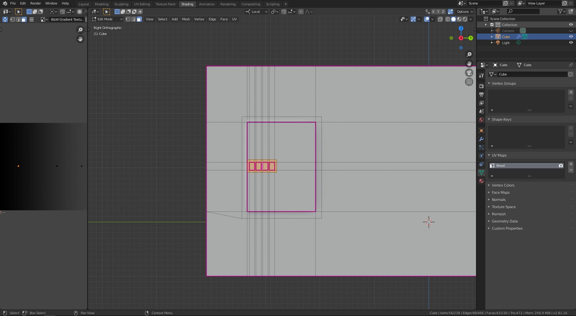
As you can see in the screenshot below, I've cut additional geometry to surround your smaller objects and moved their UV mapping so that they shared the same bevel width.

Cuts

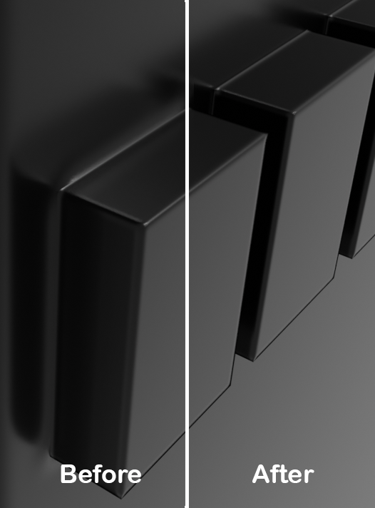
Here's a comparison of before/after:

Render

$\endgroup$
2
  • 1
    $\begingroup$ He he ... just finished writing an explanatory answer myself... and you've put it a lot better than me. Looks better too (sound of tearing paper) :D $\endgroup$
    – Robin Betts
    Commented Dec 28, 2019 at 10:29
  • $\begingroup$ lol sorry about that $\endgroup$
    – stphnl329
    Commented Dec 28, 2019 at 14:12

You must log in to answer this question.

Not the answer you're looking for? Browse other questions tagged .