1
$\begingroup$

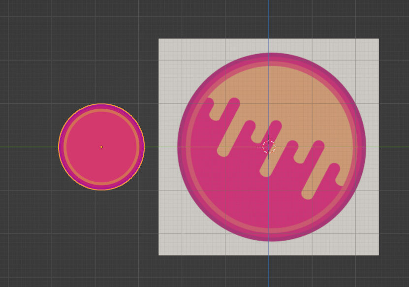
I started working on a project for a friend and it involve shading for a sphere

enter image description here

I already got the outline done but i have no idea how to do the wavy center. I tried messing around and searching if it had been already done but i must have the wrong wordding because i can't find anything.

Could you please help me with this ?

enter image description here

Here's the outline shader if you need it.

$\endgroup$
4
  • $\begingroup$ The thing on the right is already an image, isn't it? I would just use that as a texture. Is there a reason you cannot do this? $\endgroup$
    – bstnhnsl
    Commented May 10, 2022 at 13:17
  • $\begingroup$ the object on the left is a UV sphere. Does it work with a square texture like that ? $\endgroup$
    – DieuDuFeu
    Commented May 10, 2022 at 13:23
  • 1
    $\begingroup$ What's the expectation for the 3d object? Should it be able to rotate? (Kickair's answer is great, btw) $\endgroup$ Commented May 10, 2022 at 19:03
  • 1
    $\begingroup$ @DieuDuFeu Yes. The Shape of the Texture doesnt matter. I would have suggested something similar to KickAir8p's solution. Does that work for your usecase? $\endgroup$
    – bstnhnsl
    Commented May 10, 2022 at 20:52

2 Answers 2

3
$\begingroup$

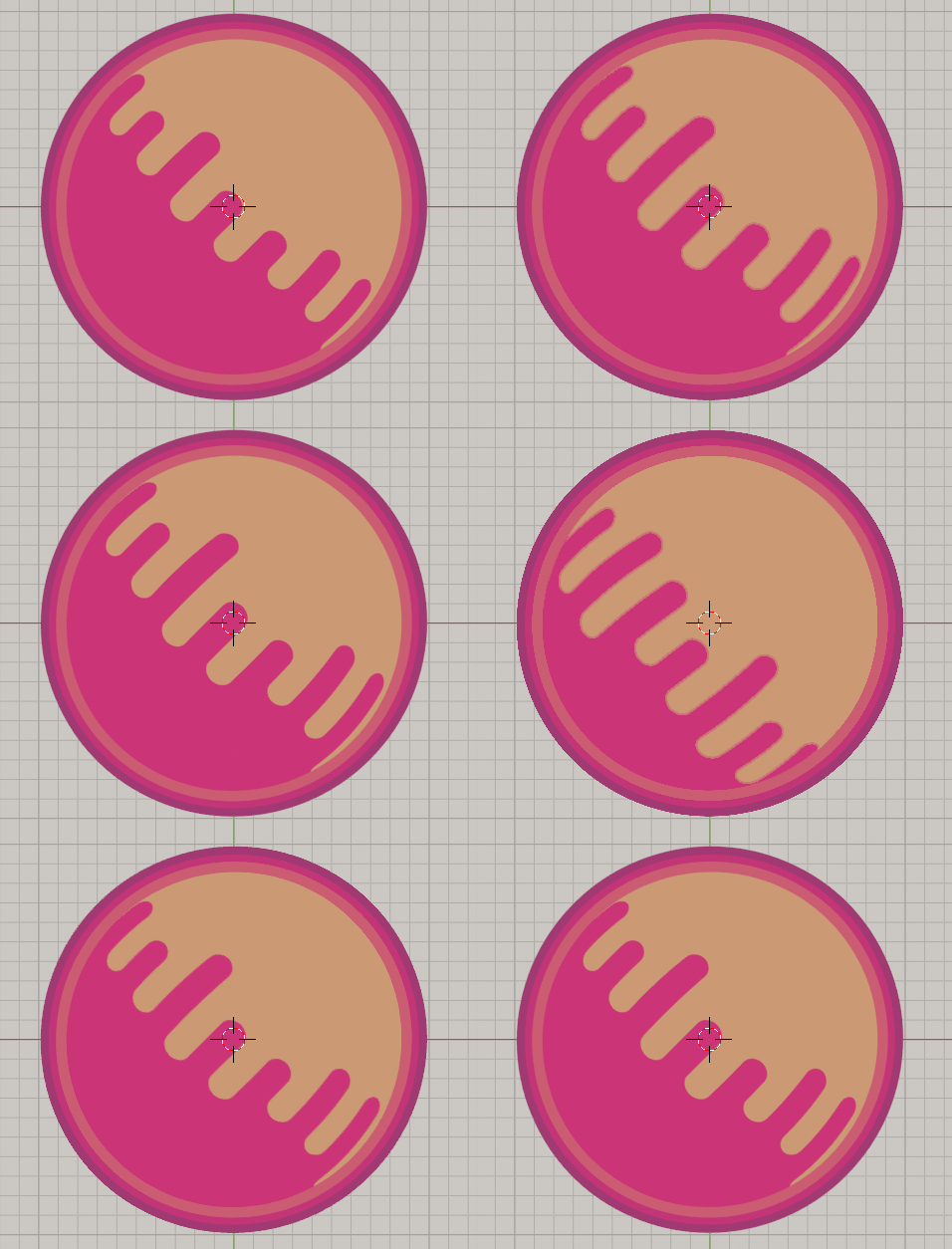
Since there's a comment from the asker indicating that a solution using an image texture could be acceptable, this uses a drip mask that I made in Inkscape (packed into the blend, link below). It also uses both a UV Sphere and a spherized Cube:
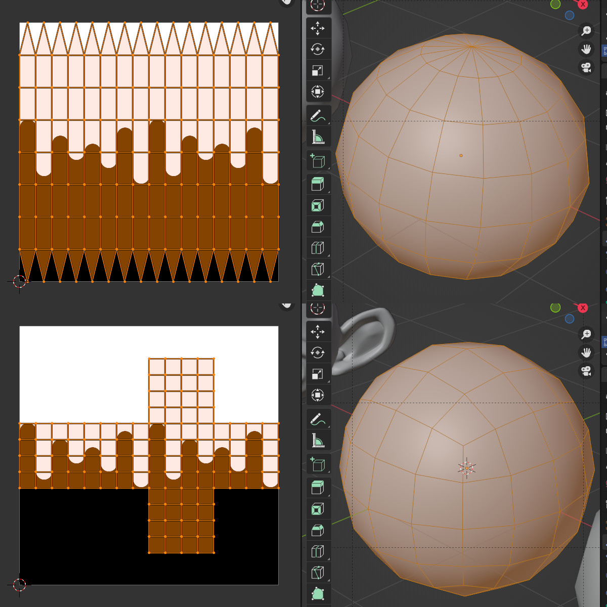
enter image description here

Below the Texture Coordinate node's UV output is used, through the Mapping node, as the Vector input of the Image Texture node. Note the distortion is different on each sphere due to the different topology and UV mapping. Although this can be alleviated somewhat by adjusting the image, an image texture (always flat) UV wrapped around a sphere will always have some distortion:
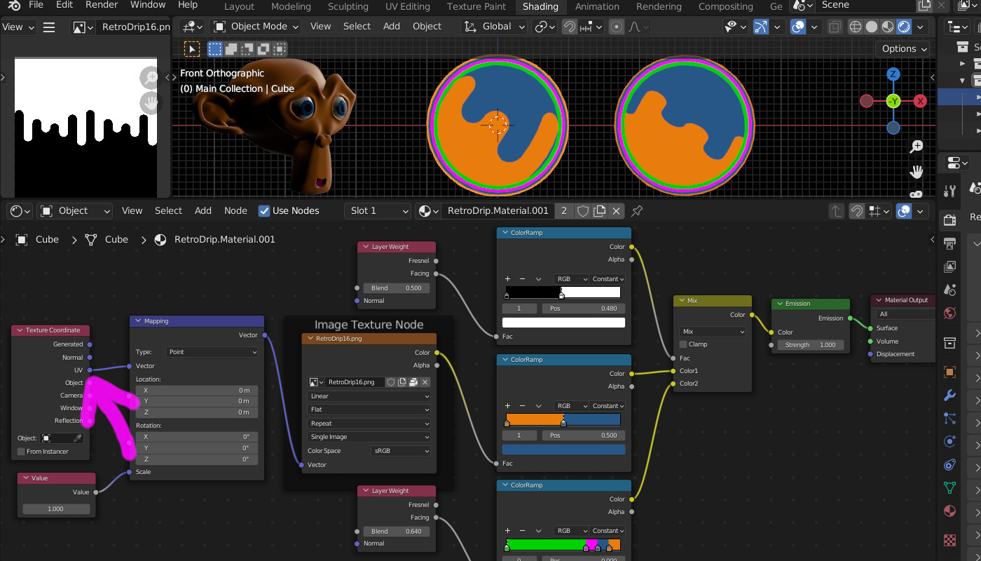
enter image description here

Below the Texture Coordinate node's Camera output is used, through the Mapping node, as the Vector input of the Image Texture node. Note that the Location info in the Mapping node positions the image correctly for only one of the spheres -- if multiple objects are to be shown, a different material with different Mapping info will need to be used for each:
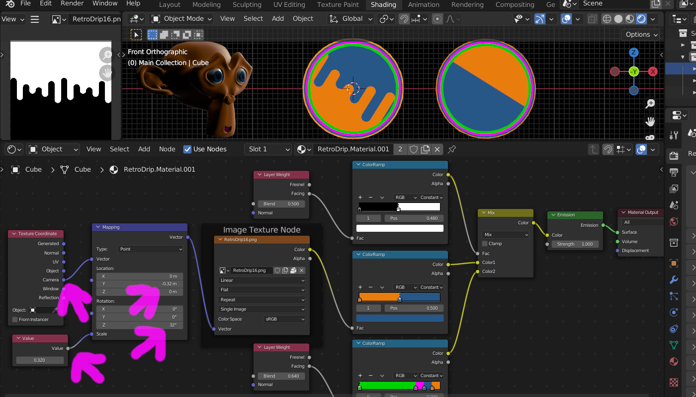
enter image description here

$\endgroup$
2
$\begingroup$

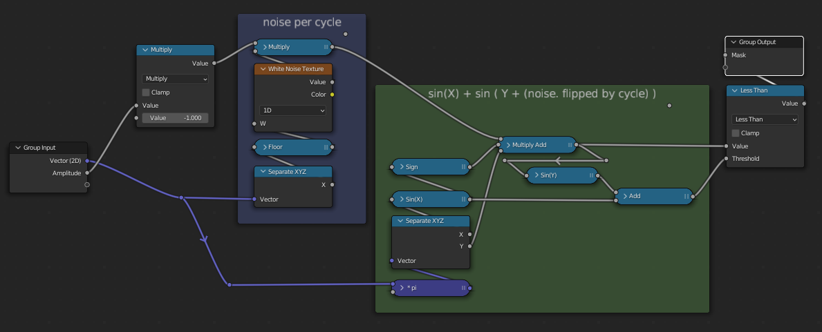
Trying to crunch this down to the minimum number of nodes, for a procedural version.

enter image description here

This way:

enter image description here

  • Takes the basic function y < (sin(x) + sin(y)) to give the wave on the left, above.
  • Uses floor(x)to quantize 1D noise into [random 0-1] stripes, that will be used to shift the Y coordinate, per cycle.
  • Multiplies the quantized noise by the sign(sin(x)) to ensure positive cycles are sent up, and negative cycles are sent down.
  • Adds the noise it to Y, before sending it to the function.

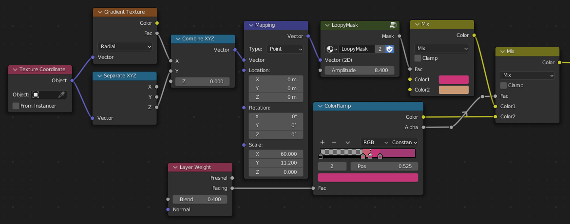
Here's a material which uses the radial angle of a sphere as X and the sphere's Z as Y:

enter image description here

It also uses Layer Weight to put the fixed colour rim on the sphere..

enter image description here

If you want the strictly flat, graphical look of your illustration, you could put this mask into the XY of Camera Space, as suggested by KickAir

$\endgroup$

You must log in to answer this question.

Not the answer you're looking for? Browse other questions tagged .