3
$\begingroup$

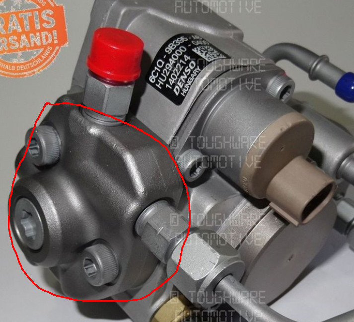
What is the best method in Blender to model the area in the red circle below? I have tried a number of methods (deleting faces, using F to join edges, etc) but am not completely happy with the results. The meshes need to remain clean and relatively low-poly. Any advice would be appreciated...

Thanks,
Jeff

enter image description here

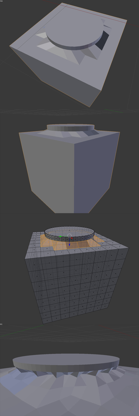
Here you can see what I'm experimenting with, attempting to join a cylinder smoothly to a cube. I've taken some edges from the cube, and attached them to the cylinder. However, when I add the Subdivision Surface, the faces "buckle in" somewhat (Bottom Image)

enter image description here

$\endgroup$
7
  • 1
    $\begingroup$ Which particular part of the process causes you trouble/you are not happy with? $\endgroup$ Commented Sep 19, 2016 at 20:15
  • $\begingroup$ Hi Ray, thanks for your response... Well, I'm not happy with the result...the mesh looks a little awkward and not perfectly smooth in the end. The joining edges part works out very easily, but when I apply the Subdivison Surface, I'm not happy with the look. Is the above method the best way to create this sort of shape, or is there a better way? Thanks, Jeff $\endgroup$
    – Jeff Alu
    Commented Sep 19, 2016 at 20:36
  • $\begingroup$ I suggest adding pictures of what you have so far by using the edit link under your question so people might be able to diagnose why adding a Subsurf to your model might not be working so well. $\endgroup$ Commented Sep 19, 2016 at 20:48
  • $\begingroup$ Hi Ray, are you saying that my method above is the best way to achieve this? Just want to make sure I'm not overlooking something obvious! :) $\endgroup$
    – Jeff Alu
    Commented Sep 19, 2016 at 20:53
  • 1
    $\begingroup$ I'm not currently saying anything about the method, I just think you need to show in your question what you've got so people will be able to help you better, whether that's improving your current method or suggesting a new one. $\endgroup$ Commented Sep 19, 2016 at 20:57

2 Answers 2

1
$\begingroup$

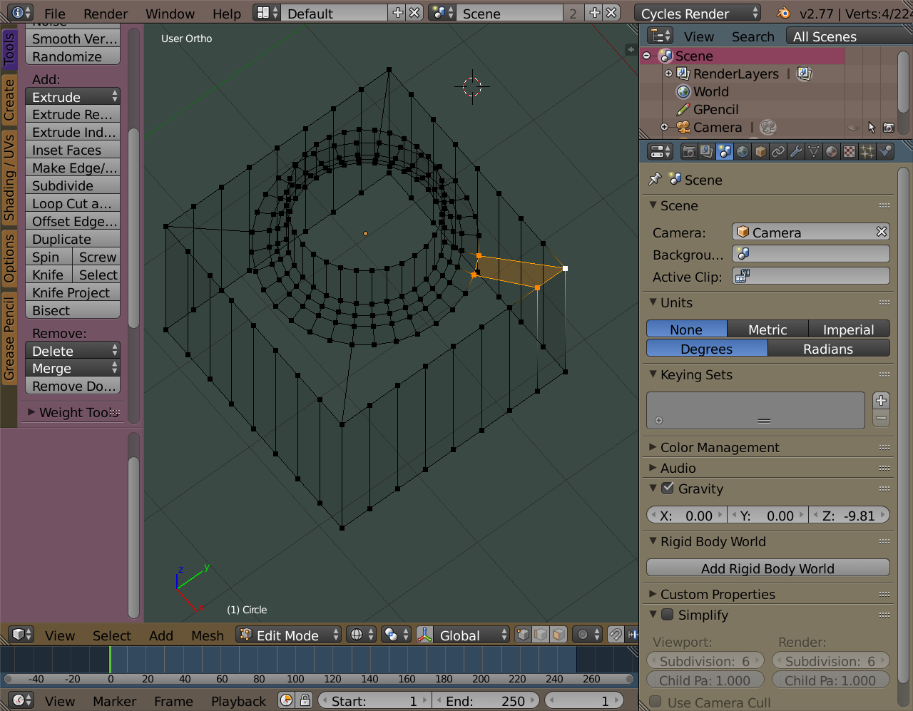
In that example I worked only with the cylinder and extended it out and squared it off to look like a cube edge .. But if you want to attach the cylinder to a separate cube and want it to join it properly, you have to match vertices.

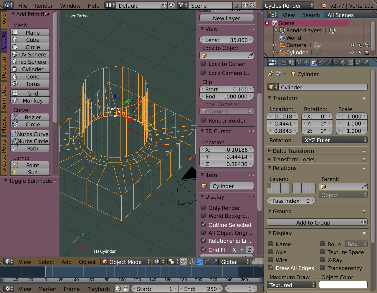
Remove the faces off the top of the cube and then add or remove vertices to the cube along the edge so both the cylinder and the cube have the same number where they meet. Then you fill in the faces, bridging the gap .. I have an example. The cylinder has 32 vertices along the edge and the cube began with 4. I connected the corners to the cylinder using edges, that's 4. THen I added 7 vertices on each side of the cube. That gave the cube 32 as well (7x4 +4). Then I began filling the gap.

If you look at bolts in the add-on 'bolts' you'll see they are made the same way basically where the screw part meets the head .. the cylinder is extended along the flat to the edge and the hexagonal edge vertices have to match the cylinder (ie top of the screw).

Also I have a quick example of attaching two shapes very roughly similar to your die cast example. I attached them (this involves some editting where they meet) and THEN I worry about extending the flat area which I started to do. Hope it helps.

Oh ya, I saw the comment about retopo ... that's a good method too .. In essence it's joining various shapes and then laying over it a mesh you construct. You have know about how to lay meshes you build on top of objects which is what retopo is .. anyway .. good luck
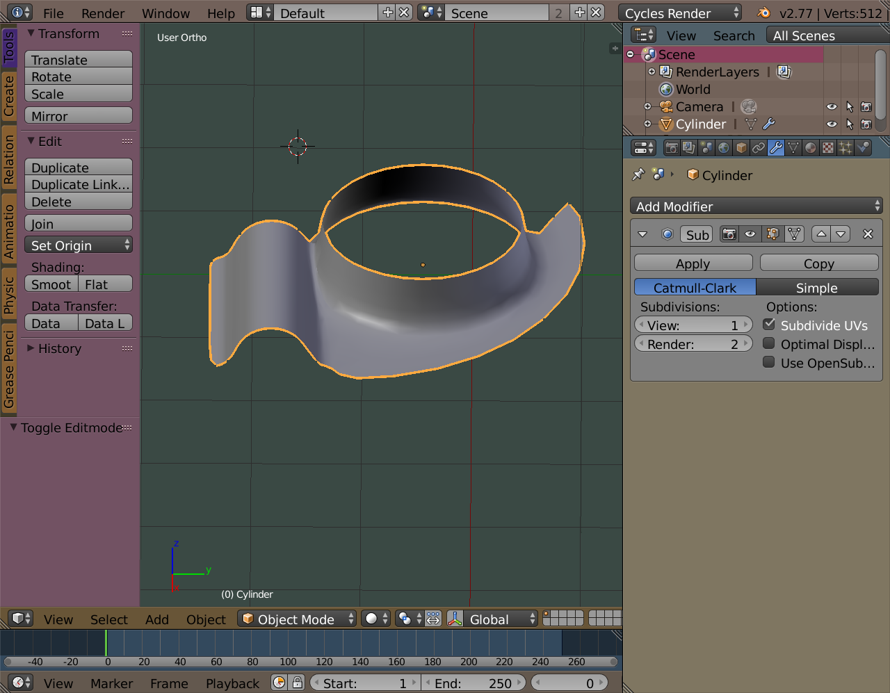
enter image description here

enter image description here

$\endgroup$
1
  • $\begingroup$ Thank you for this very detailed description as well as examples! $\endgroup$
    – Jeff Alu
    Commented Sep 21, 2016 at 14:41
0
$\begingroup$

Cylinder to cube .. well, the thing is I would maintain the cylinder geometry as it flattens out .. so would scale out one end a bit before I worry about defining the cube part .. Here's an example. See how the cylinder where it flattens out is still radiating circles .. then I square it off at the cube edges.

enter image description here

$\endgroup$
5
  • $\begingroup$ And ah .. I would take the same attitude to your other example.. model the shapes separately, radiate they out where they flatten so their geometry is not compromised, and then join them to each other manually. $\endgroup$
    – nanopossum
    Commented Sep 20, 2016 at 5:16
  • $\begingroup$ I will give this a try, thanks for the advice! $\endgroup$
    – Jeff Alu
    Commented Sep 20, 2016 at 15:25
  • $\begingroup$ How did you get your cube to match the geometry of the cylinder? $\endgroup$
    – Jeff Alu
    Commented Sep 20, 2016 at 15:58
  • $\begingroup$ Would love to know how you're doing your "squaring off", that actually seems like a better way to go! $\endgroup$
    – Jeff Alu
    Commented Sep 21, 2016 at 14:39
  • $\begingroup$ There's a trick for aligning vertices in a row. You can align vertices along any axis. To do it so they form a straight line along say the Y axis .. select vertices, then hit S (for scale) then 0 (zero) then X. All vertices selected will then have their X=0. $\endgroup$
    – nanopossum
    Commented Sep 22, 2016 at 3:50

You must log in to answer this question.

Not the answer you're looking for? Browse other questions tagged .