(Using Blender 3.6.8)
(NB: documentation to be continued...)
Objective
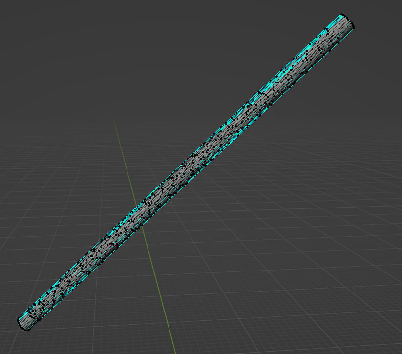
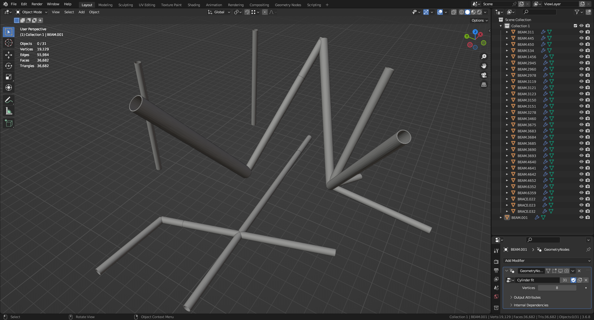
The initial configuration is a collection of hollow pipes. Each pipe is an object modelled with a dense triangular mesh, as illustrated in the following figure:
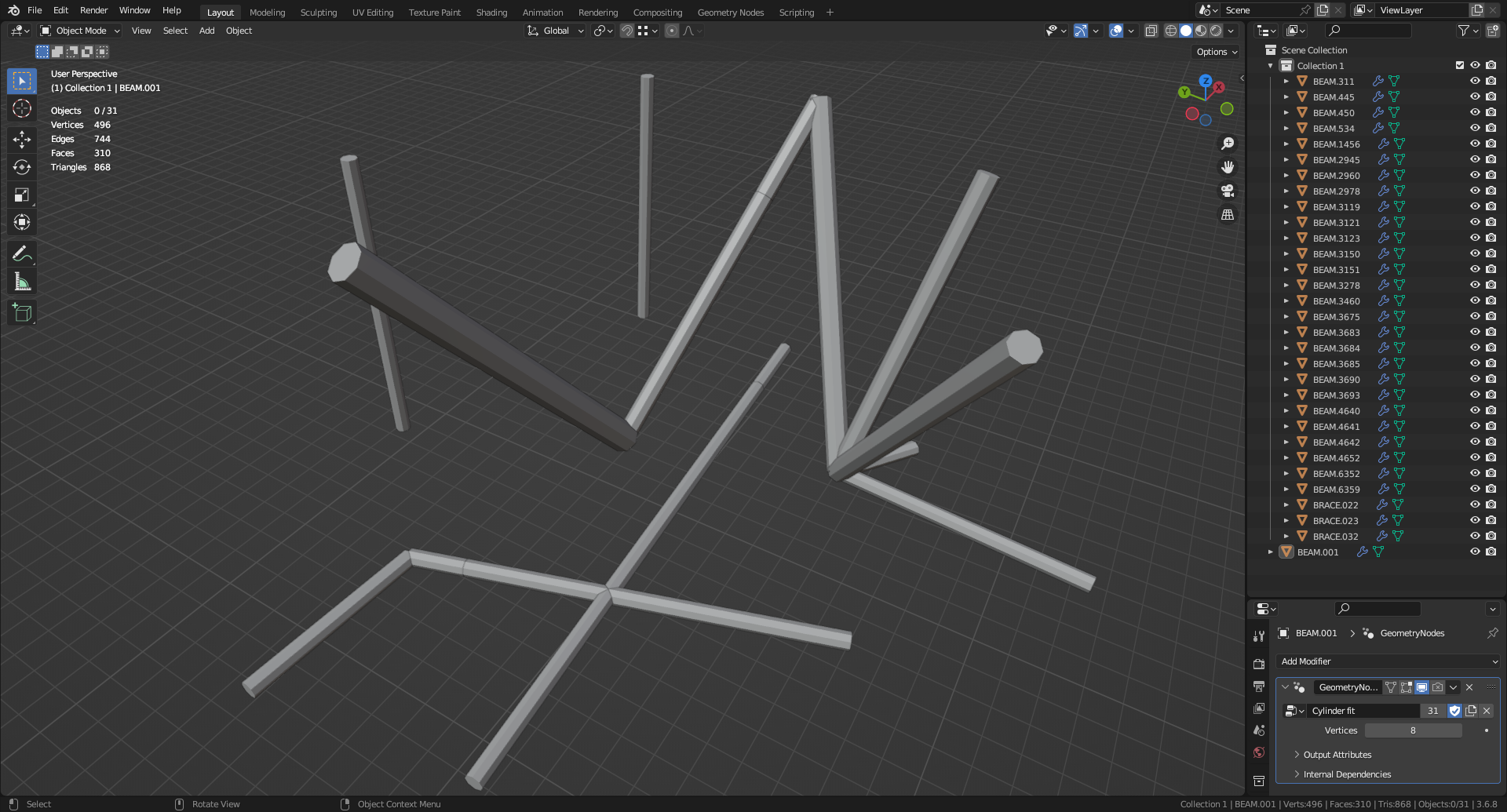
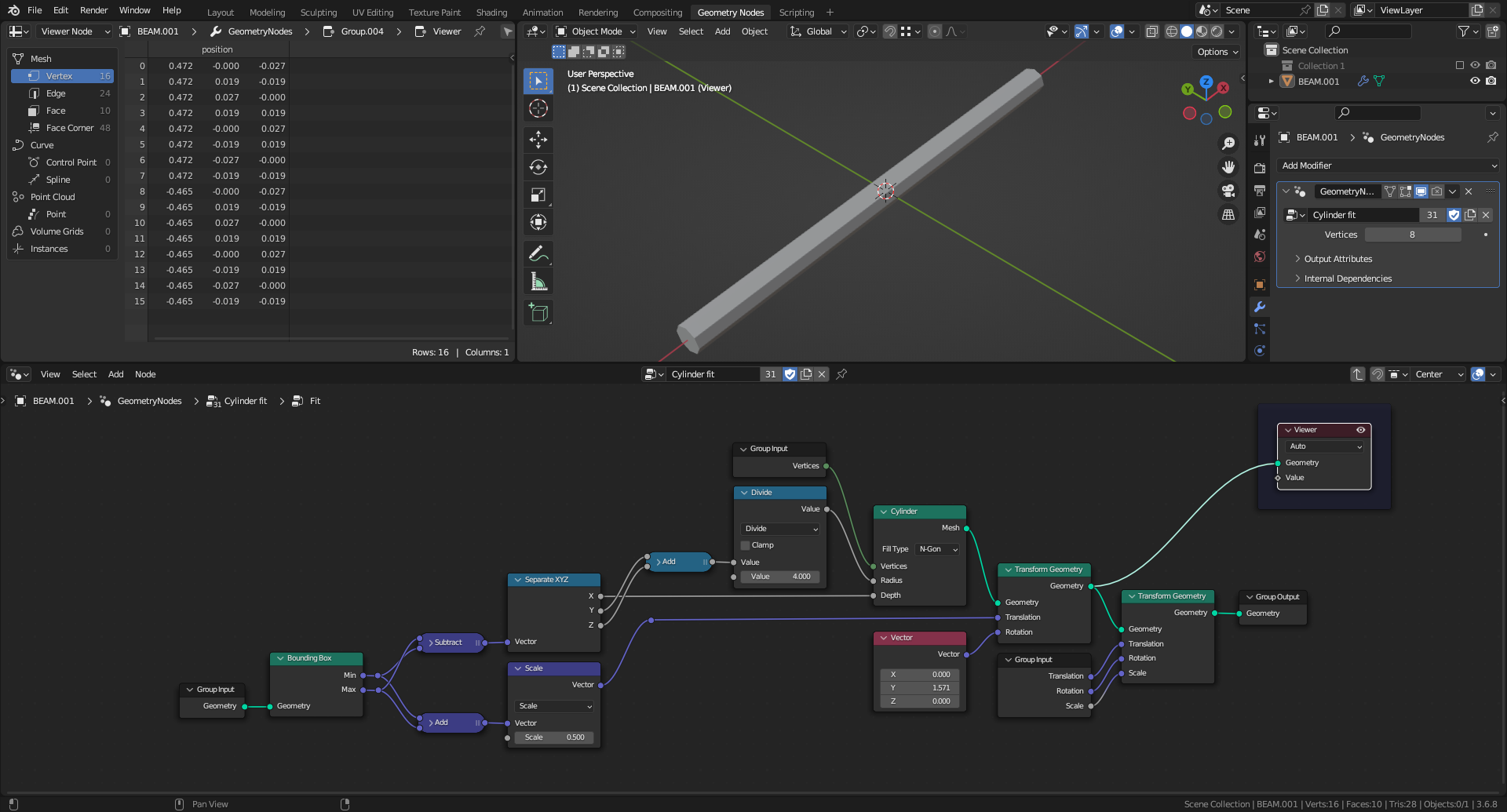
The objective is to replace each mesh by a full Cylinder, keeping its dimensions (length and radius), position and orientation, as shown below:
Approach
A GeometryNodes modifier is attached to a pipe object. After setup, it can be easily transferred to all the others using the menu entry Object > Link/Transfer Data > Copy Modifiers in Object Mode.
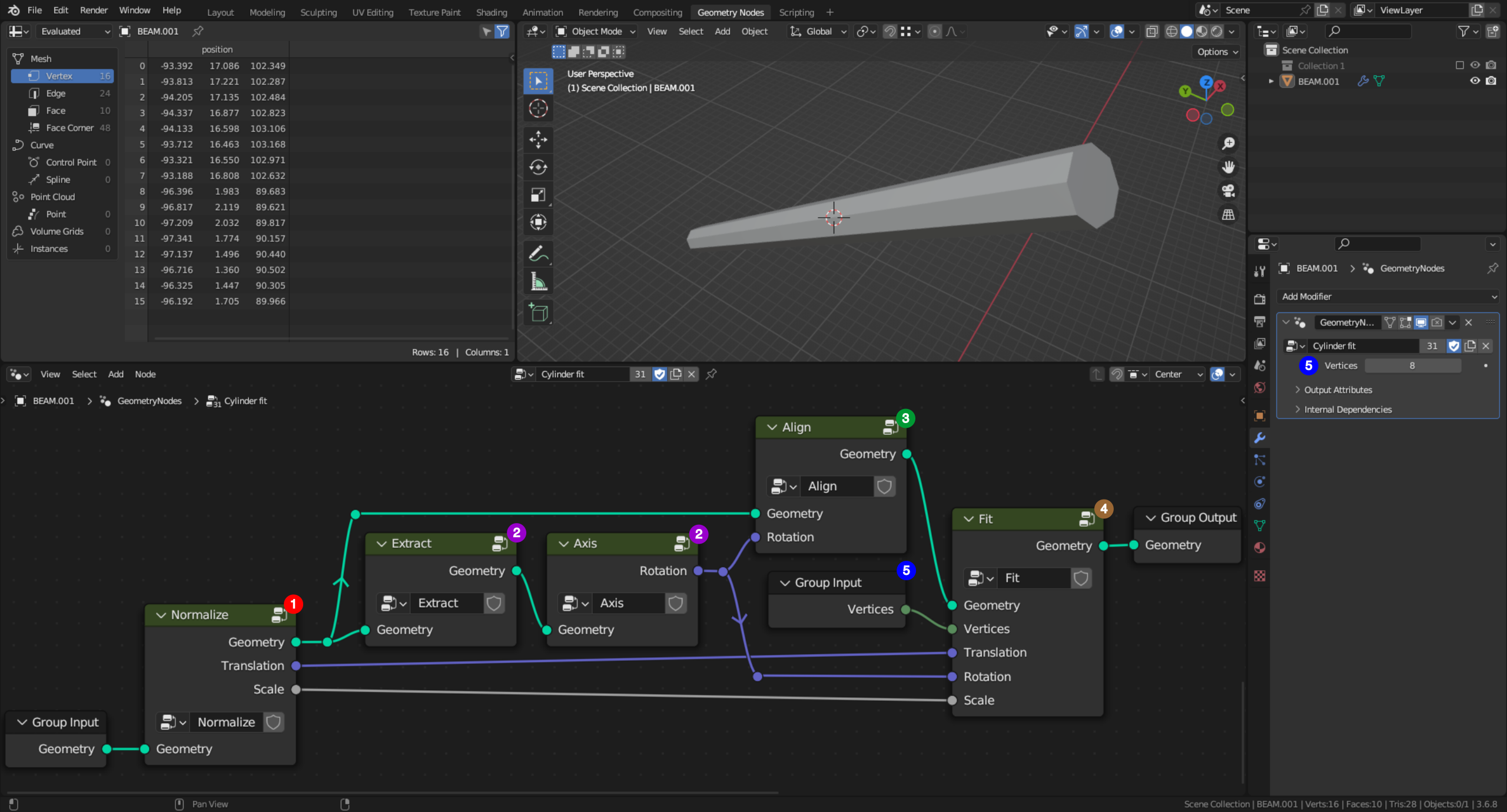
1. Because pipes are varying in aspect ratio and size, the original mesh is centred on the object origin and it is scaled such that its largest dimension is about unity.
2. The inner surface is extracted to compute the axis of the pipe.
3. The normalized pipe is aligned with the world X axis to compute its length and radius.
4. A Cylinder Mesh Primitive node is used to make a new mesh, that is scaled, rotated and translated to replace the original one.
5. The cylinder number of vertices is a user-defined parameter as an Input attribute. For the demonstration, it is set to 8.
GeometryNodes modifier
(NB: In the following pictures of node groups, dark blue frames are for visualisation only. They are not part of the process.)
Normalizing the data
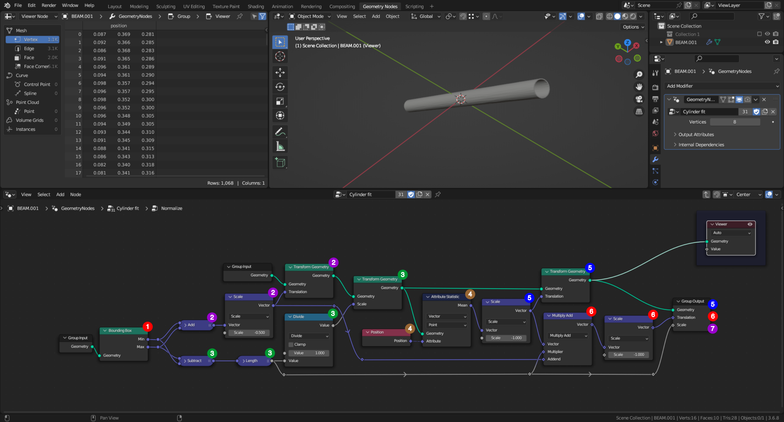
1. The Bounding Box of the tube is used to centre, then to normalize its vertices position, to minimize round-off errors. Because Translation is applied after Scaling by a Transform Geometry node, two such nodes are required.
2. The centre of the BoundingBox (labelled $C$) is computed as the mid-point between opposite corners. This point should move to the object origin (labelled $O$) (NB: Objects origin is set at the world origin in the provided test-case). This is why the scaling factor is negative, to compute the Translation (i.e. $\vec{CO}$) applied by the first Transform Geometry node.
3. A characteristic dimension of the tube is computed as the Length (labelled $\lambda$) between the BoundingBox opposite corners. Vertices position is scaled by $\frac{1}{\lambda}$, such that (X,Y,Z) coordinates are between -1 and +1, using the second Transform Geometry node.
4. The tube axis identification requires one point of this axis (labelled $G$). Assuming that the tube inner and outer surfaces are evenly discretized, such a point position can be reasonably approximated as the averaged Position of all vertices. So $\vec{OG}$ is computed as the Mean value returned by an Attribute Statistic node.
5. Using a third Transform Geometry node, the scaled tube vertices are Translated by $\vec{GO}$, such that $G$ moves to the object origin ($O$). Consequently the Output Geometry is such that the sought axis goes through the origin of the original tube.
6. To move the vertices of the cylinder generated at the end of the process back to the position of the original tube, the overall Translation vector $\vec{OG}$ must be preserved. It is computed by a Multiply Add followed by a Scale vector math node as $-(\vec{CO}+\lambda \vec{GO})$, as a consequence of the two successive translations. The $\lambda$ factor is required because $\vec{GO}$ is computed at step 4 after the scaling by $\frac{1}{\lambda}$.
7. To scale the cylinder generated at the end of the process back to the size of the original tube, $\lambda$ must be preserved also.
Extracting the inner surface
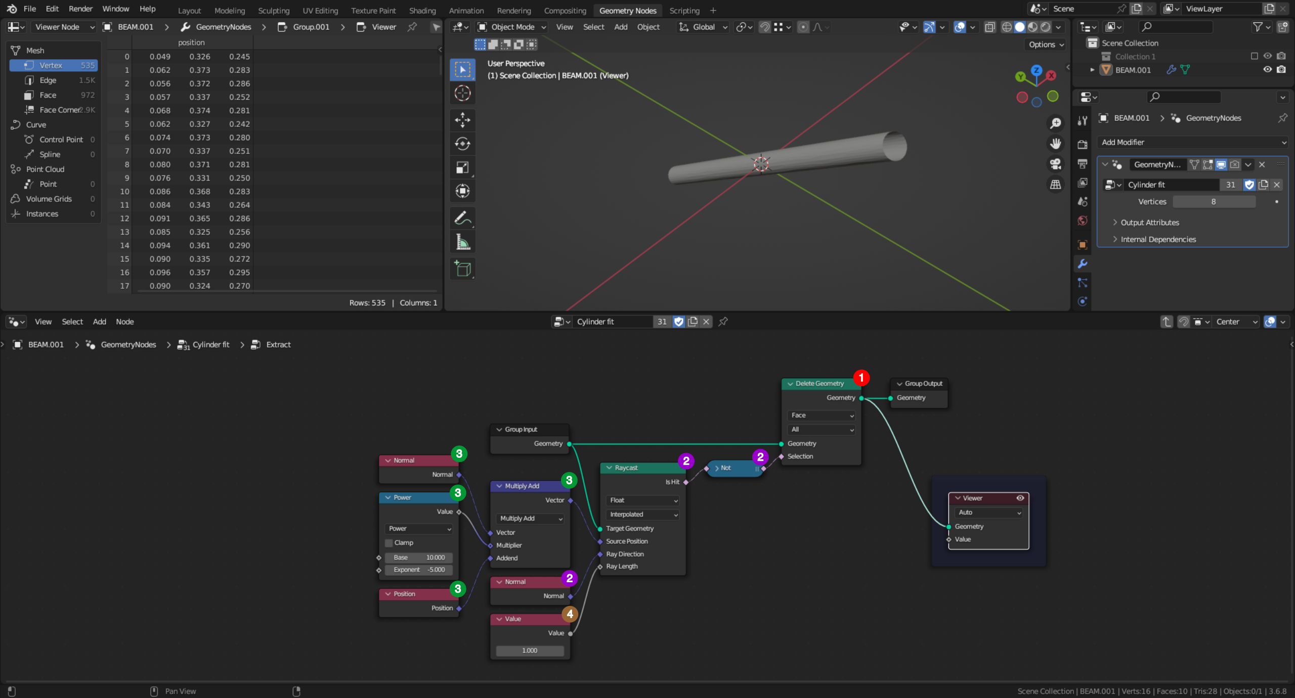
1. Only faces inside the tube are kept using a Delete Geometry node set in Face domain.
2. Its Selection mask is based on a Raycast node applied to the tube onto itself, specifying the Normal as Ray Direction. Because the normal of top, bottom and outer faces are pointing away from the object, the output socket Is Hit is False for such faces. So a Not boolean node is inserted to tag these as True for deletion.
3. The Source Position must be slightly shifted along the Normal (labelled $\vec{n}$) to avoid confusion between source and target. It is computed by a Multiply Add vector math node adding $\varepsilon \vec{n}$ to the face centre Position, with $\varepsilon=10^{-5}$.
4. Because the geometry is previously normalized, the Ray Length can not exceed 1. This value is hardcoded.
Extracting the axis
It is assumed that after the data normalization, the tube axis is going through the object origin $O$. Let $\vec{d}$ be a unitary vector aligned with this axis. Let $M_i$ be the centre of a face extracted previously, and $\vec{n_i}$ be the normal to this face. $\vec{d}$ and $\vec{n_i}$ are orthogonal. Consequently, $\vec{OM_i} = (\vec{OM_i} \cdot \vec{d})\ \vec{d} + (\vec{OM_i} \cdot \vec{n_i})\ \vec{n_i}$. Let $D_i$ be the point defined as $\vec{OD_i} = (\vec{OM_i} \cdot \vec{d})\ \vec{d} = \vec{OM_i} - (\vec{OM_i} \cdot \vec{n_i})\ \vec{n_i}$. It would be on the tube axis, notwithstanding discretization and round-off errors. So an averaged direction $\vec{OD}$ is favoured. It is defined as $\vec{OD} = \sum_i^N s_i \vec{OD_i}$, with $N$ the number of faces and $s_i=\pm 1$. The factor $s_i$ is required because point $O$ being at half of the axis, vectors $\vec{OD_i}$ of both halves of the tube are pointing in opposite directions. Without this, the average could be zero. (NB: If needed, $\vec{d}$ could be computed as $\vec{d} = {\vec{OD}}/{\|\vec{OD}\|}$).
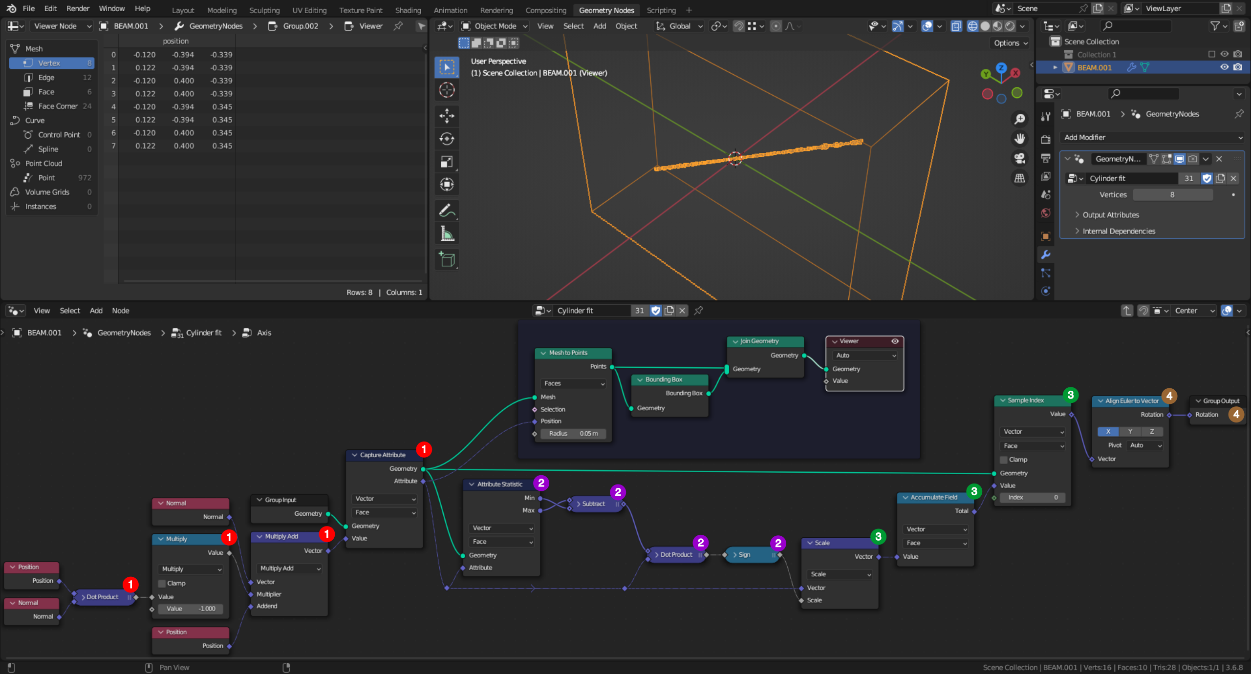
1. $\vec{OD_i}$ is computed by a sequence of Dot Product, Multiply and Multiply Add nodes. This computation is triggered by a Capture Attribute node set in Face domain.
2. To compute $s_i$, the opposite corners of the box bounding the $D_i$ point cloud are recovered with an Attribute Statistic node set in Face domain. By subtracting these, a reference direction $\vec{a}$, which might be different from $\vec{d}$, is computed. Eventually, $s_i$ is defined as the sign of $\vec{a} \cdot \vec{OD_i}$.
3. $\vec{OD} = \sum_i^N s_i \vec{OD_i}$ is computed by an Accumulate Field node set in Face domain through its Total socket. As this output is the same for all faces, a single value is captured using a Sample Index node set in Face domain, where the Index being irrelevant is hardcoded as 0.
4. To align the cylinder of X axis generated at the end of the process back with the axis of the original tube, $\vec{d}$ is converted in a Rotation using an Align Euler to Vector node. Its setup is such that the X axis is aligned with $\vec{d}$.
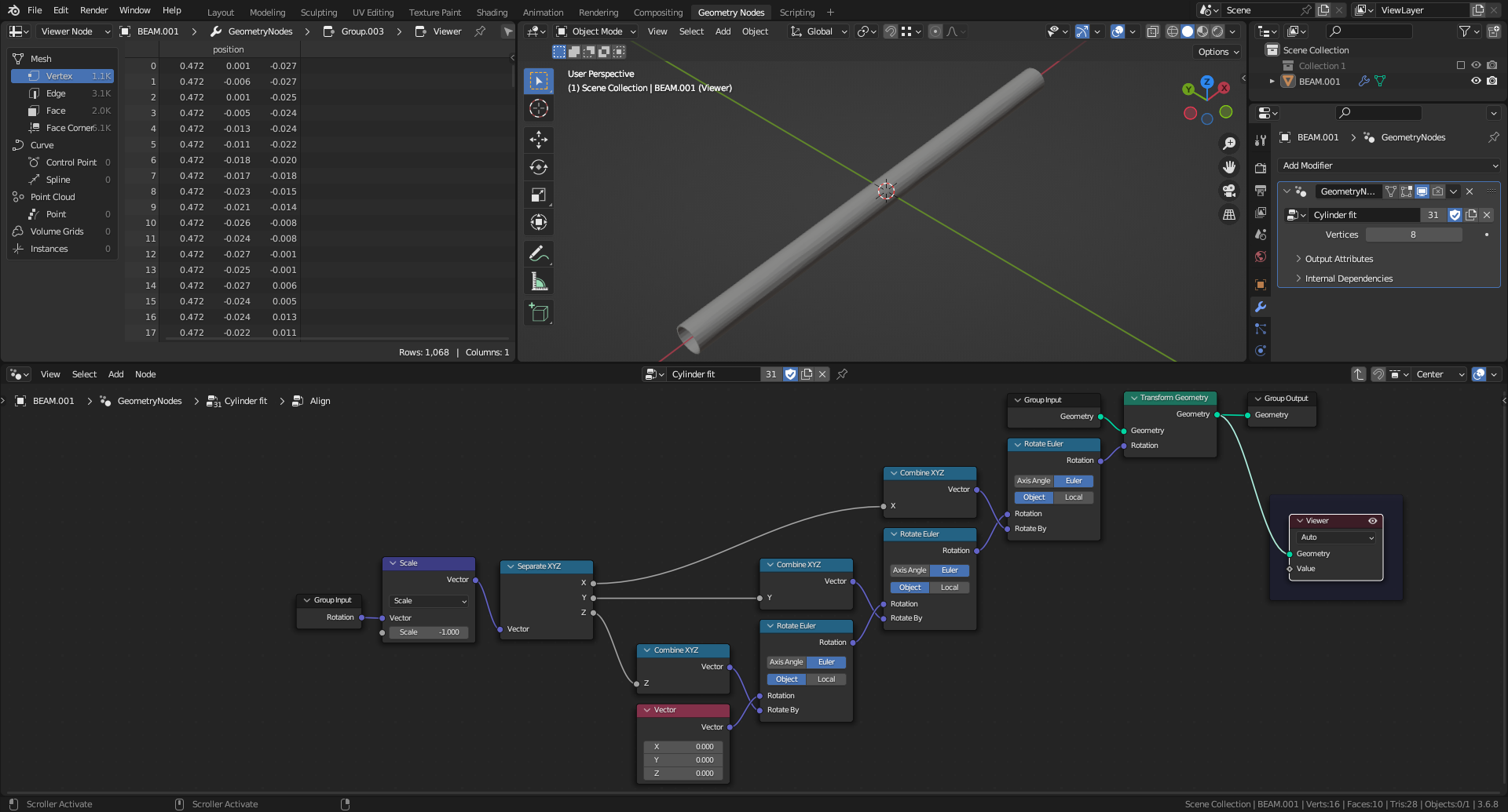
Aligning along X axis
Fitting a cylinder and transforming it back
Resources

