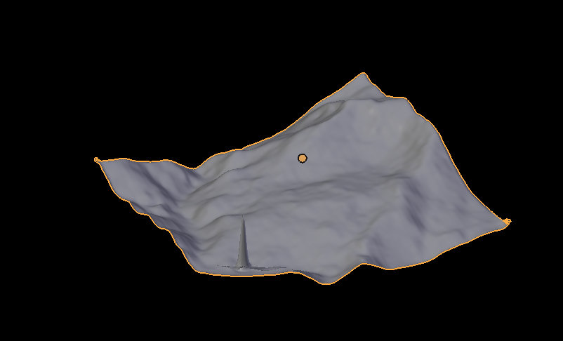
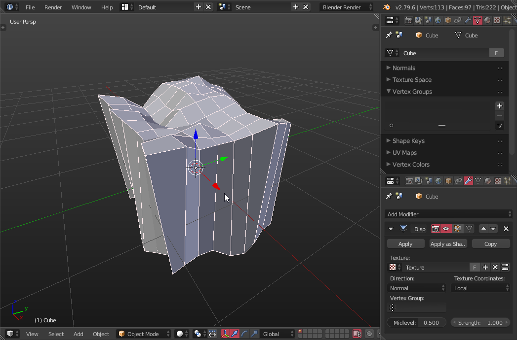
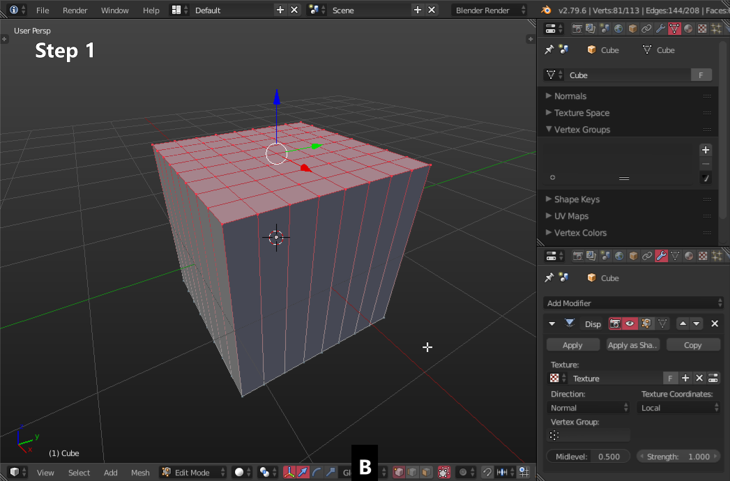
I have a nice piece of topo mesh but I want it to be the top face of a cube to make the object be a block with simple grey sides and bottom. I suppose I could make a separate cube then somehow fit the terrain onto the top but these must be a simpler way. I have tried E extrusion but can't get the hang of it.
2 Answers
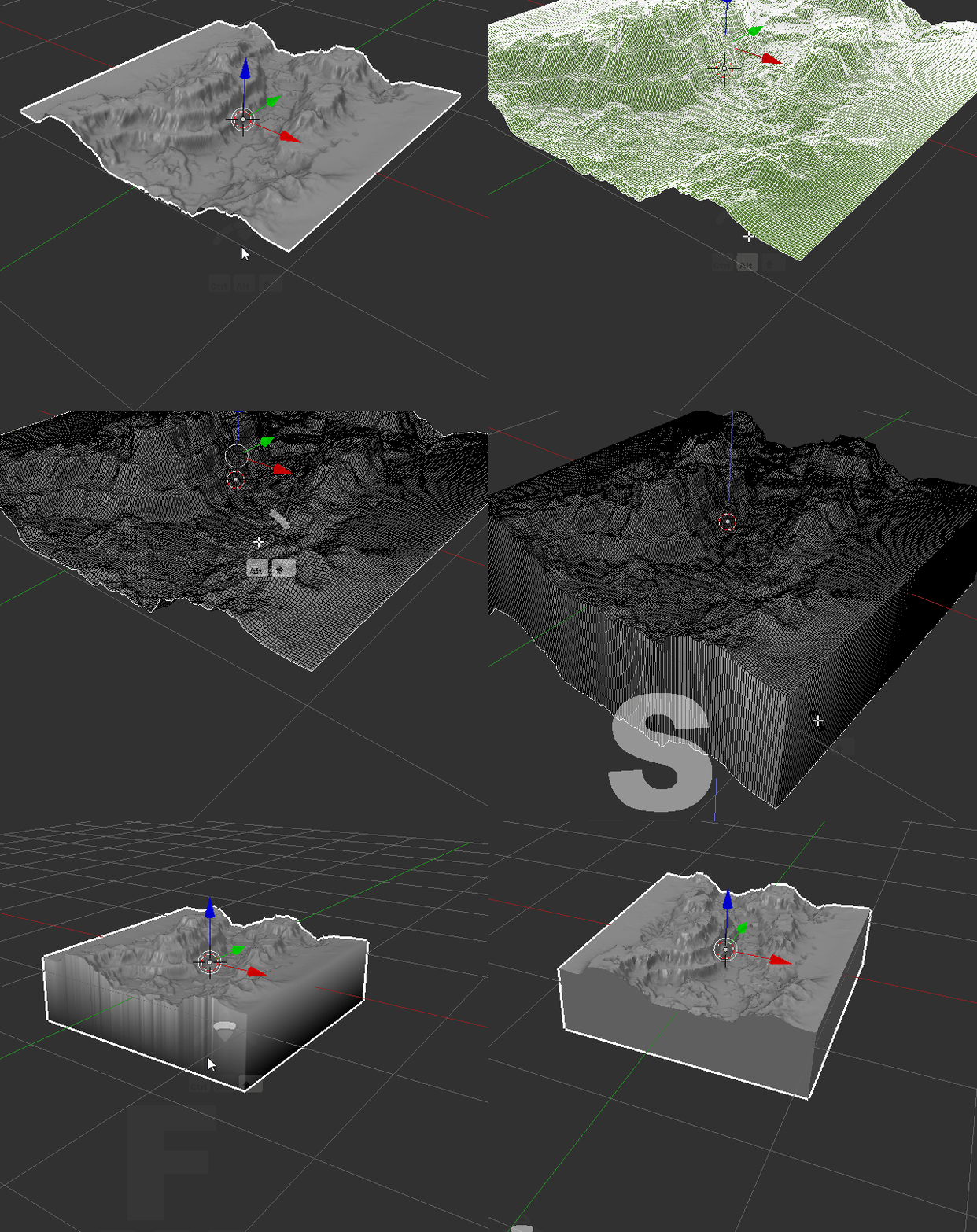
Enter edit mode, select the edges all around your mesh:
Use AltRclick to select an edge loop, or CtrlRclick to select a path between your previous selection and the new one.
Once you have selected all that, simply extrude down:
E for extrude, press Z to constrain it to the Z axis, then validate with Lclick.
Then make this extrusion flat by scaling it on Z to zero:
S for scale, then Z, then Numpad 0 and validate.
Not you just have to make a face from that edge loop, with F.
EDIT :
It looks like your mesh is deformed by a modifier, I would guess a displace modifier. I guess it's how you obtained the shape of the top. The issue is that the modifier affects your whole object, even the parts you want to keep flat.
So we need to restrain the area of action of this modifier.
A simple way to do that is to use a vertex group.
For the sake of demonstration, I recreated your setup (at least what I guessed out of your pictures):
As you can see on the right, I show both the modifier settings and the "vertex group" panel which can be found in the Object Data tab (the triangle icon).
First, let's create the vertex group we need:
- Enter edit mode
- In vertex selection, select only the top part of the mesh we want to deform
- Hit CtrlG to assign the vertices to a new group, hit the confirmation button spawned under your cursor.
- You can see the created group in the vertex group panel, I rename it "Deform Mask" for the sake of clarity.
- In the modifier's settings, select the Deform Mask group in the vertex group input.
Now it deforms only the top vertices, but we need to do one more thing. You will notice that the top vertices are still being moved on X and Y axes, making the vertical faces deformed instead of flat.
This is because of the direction of the deformation. By default, this modifier deforms in all directions according to the faces's normals. We want in this case to move vertices only up and down, so let's change the direction to Z.
And here we go:
-
$\begingroup$ Sorry, tried this many times, many variants, my extrusion downward refuses to exhibit vertical sides, the sides get distorted. But you put an "S" after you extrude, don't understand this. $\endgroup$ Commented Nov 23, 2018 at 23:52
-
$\begingroup$ You have to press Z while extruding to constraint the extrusion to the Z axis. Depending on your mesh, sometimes Blender will already constraint your extrusion to the wanted axis (you can see that because he highlights the concerned axis), in which case you don't need to manually constraint. About S, as I said it's for the scale. If you 'scale to zero" something, it basically crushes it flat. Here I use a scale to zero on the Z axis in order to perfectly align all the vertices on Z. $\endgroup$– Lauloque ♦Commented Nov 24, 2018 at 19:52
-
$\begingroup$ I’m good all the way to the S. What is it I select before the S Z numpad0 to crush the sides to vertical planes? I tried Shift-Alt-rmb but that doesn’t do it. I am not familiar with the mouse interface you are using so need the more basic commands. $\endgroup$ Commented Dec 1, 2018 at 4:44
-
$\begingroup$ I don't know what to say. I gave you the most basic and simple procedure. It has nothing to do with the interface, it's just keystrokes. Just keep doing what I described and it just will work. Unless you do something else, in which case, either start from the beginning, either explain exactly where you are and what you did. $\endgroup$– Lauloque ♦Commented Dec 2, 2018 at 10:08
-
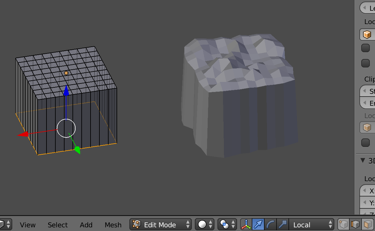
$\begingroup$ Ah, frustration, surely my lack of experience, but I added an image to the original question above showing the screen after extrusion (left). Then I enter S Z 0 (last from the numbers on my mac keyboard which emulate numpad) and, lo, I get what I don't want on the right. I've tried changing global/local, edge/face, same result... $\endgroup$ Commented Dec 19, 2018 at 2:27
Bmesh script.
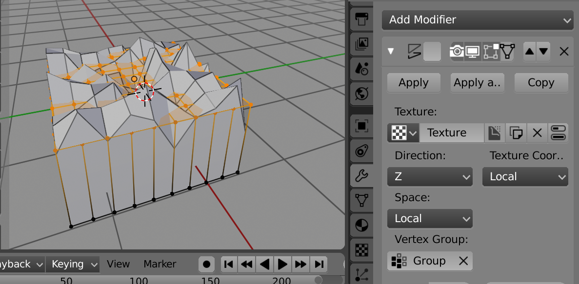 Test 10 x 10 grid with voroni z displacement texture
Select plane mesh in object mode, run script.
- Extrudes face region
- Moves all verts of extrusion to a set baseline. (Edit
base_line = -1to alter. - Sets the material index of new side and bottom faces to
mat_index = 1(once again edit to suit) - If you are using a displace modifier, add all the verts of the plane to a vertex group.(Prior to running script) The plane before adding the base in image are all in vertex group "Group". Use this group in the modifier. Edit the name of this group in script
displace_modifier_vgname = "Group"The script will remove all generated verts from a vertex group if it exists with that name ``
Script
import bpy
import bmesh

base_line = -1 # z value of flat bottom
mat_index = 1 # material on sides and bottom
displace_modifier_vgname = "Group"


context = bpy.context
ob = context.object
vg = ob.vertex_groups.get(displace_modifier_vgname)

me = ob.data
bm = bmesh.new()
bm.from_mesh(me)
# extrude the surface
ext = bmesh.ops.extrude_face_region(bm,
        geom=bm.faces
        )
verts = []
for e in ext['geom']:
    if isinstance(e, bmesh.types.BMVert):
        e.co.z = base_line
        if vg:
            verts.append(e.index)
    if isinstance(e, bmesh.types.BMFace):
        e.material_index = mat_index

bm.to_mesh(me)
me.update()

if vg:
    vg.remove(verts)
-
$\begingroup$ I am on a steep learning curve to learn all of these proposals. On the script variant I am getting an error: Traceback (most recent call last): File "/Text", line 25, in <module> NameError: name 'vindex' is not defined Error: Python script fail, look in the console for now... $\endgroup$ Commented Dec 26, 2018 at 9:14
-
1$\begingroup$ Somehow lost a "." in paste-ation. Hopefully all good now. $\endgroup$ Commented Dec 26, 2018 at 10:26
-
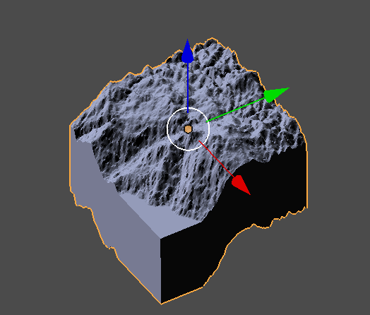
$\begingroup$ Thanks much for the script which now works. I put a screenshot of the result back up in the question (the only way I can figure to add illustrations to comments). Couple of things: the base is not flat, it mimics the top. Also the color is bluish, I guess this much be the material chosen. I can manually change these things as soon as I get some competence in vertex group assignment and exclusion which you earlier suggested. But maybe a line of code would do it. I can see that I am lacking a lot of basic skills and should probably do some tutorials before attempting these projects. $\endgroup$ Commented Dec 27, 2018 at 6:07
-
$\begingroup$ Is the vertex group assigned to the displace modifier named "Group" if not edit name in script. A screenshot of your plane and modifier settings would help. My first intention was to look for displace modifiers and use the vg name from that, however decided against. Manually Similarly to @LOlock's answer Suggest this method add a grid, add a solidify modifier, adjust the thickness, apply the modifier (effectively extruding the region) Select the boxes top vertices and assign a group. add the displace mod, using the vgroup.. $\endgroup$ Commented Dec 27, 2018 at 6:57
-
$\begingroup$ Re images, scripts or blends for comments Recommend PasteAll See the top RH corner, select image and upload. They are removed after a few months. $\endgroup$ Commented Dec 27, 2018 at 7:00

