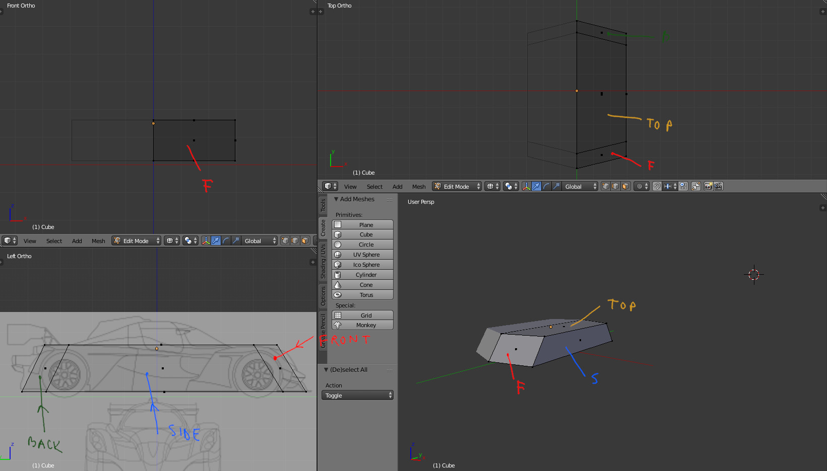
Ideally would be just to draw the other views. If you don’t have this option, you can at least measure some dimensions and use the side view as the main image. You can use that front view for side’s view depth dimensions, but make sure the images align vertically:
 Side view is the most important view on a bilaterally symmetrical object (that mirrors left to right). It’s because you see all the planes, even if distorted. For example, the front and back will project mostly on front and back angles, but not completely. The planes are at an angle to the orthographic planes and not parallel. Therefor you can see a smaller part of the from the side and even from the top. I illustrated how the mesh projects on different views here:

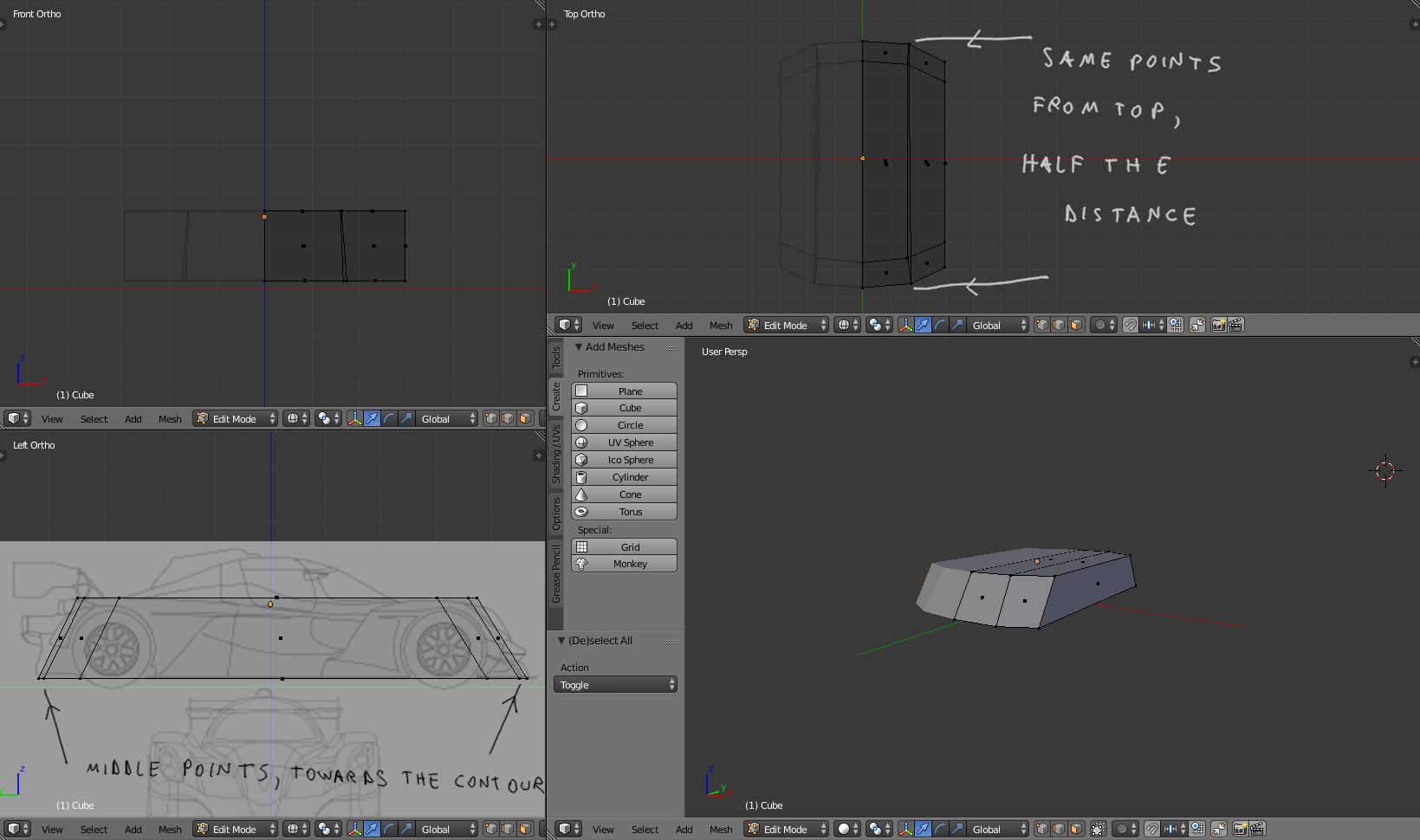
Next step is to add resolution to the planes, so they become curved. Notice that after the points are moved, from the side view, the middle edge is not at half of the plane, but rather closer to the borders. It would have been half way if the plane were flat after adding details. This is just how curved surfaces project.
 This last idea can be useful when dealing with details. In your case, the back lights from example, look like they end close the middle of the surface. (they look different from the real model though).
A good strategy is to start with more affordable models so you better develop the modelling technique. The point is this kind of situation happens and the only options are dealing with reference in perspective, or in this case, try to make the most of your blueprints so you can then make better educated guesses.


