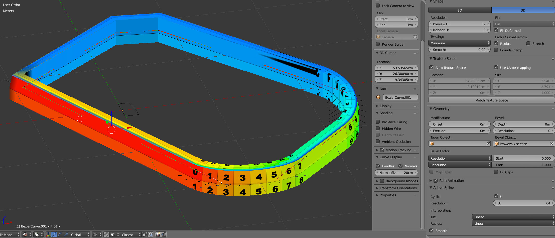
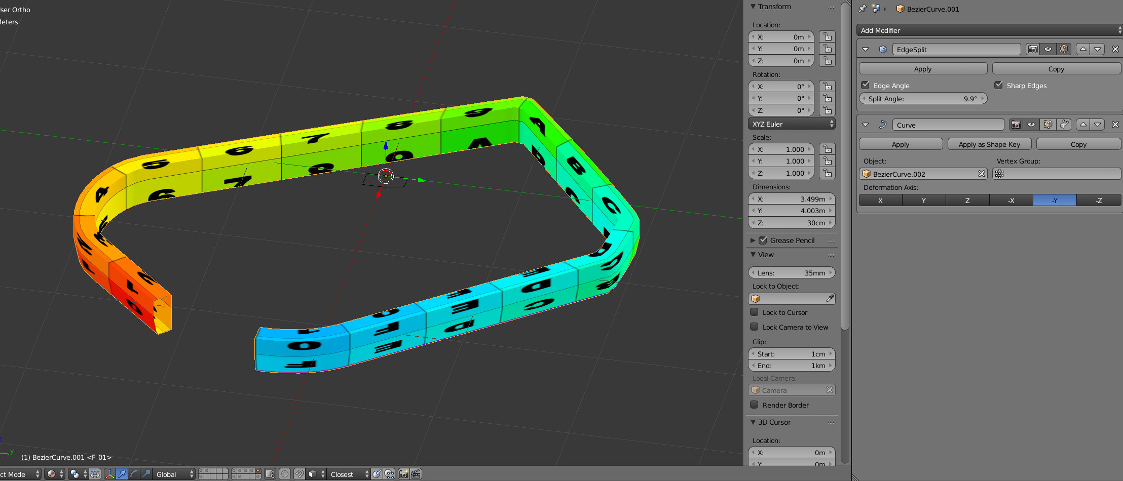
This is a task that can be solved wonderfully with Geometry Nodes.

Primarily, the Curve to Mesh node is used, which creates a mesh from your curve and your profile.
The UVs are the tricky part here.
They are not provided by the Curve to Mesh node and therefore have to be generated by yourself.
However, this is easier than it looks: Basically, you just have to transfer the generated Face Corners into a coordinate system so that you get a solid UV mapping for it.
You can use the node group directly like this, or modify it further.
I will briefly go through the steps:
Both curves are first transformed to their relevant points using the node Resample Curve and the setting Evaluated.
Next, the values for Factor and Index are collected from both curves using the node Spline Parameter.
Additionally we need the number of points of the profile, and multiplied by $4$ we get the number of Face Corners per section.
With a little bit of logic we mark the Face Corners which are located at the last point of the profile and at the last point of the curve.
The supplied indexes are in the order $0, 1, 2, 0$ and for a UV mapping we need the order $0, 1, 2, 3$.
So if the logic says that it is an endpoint, then we just put the value $1$ there instead of the factor.
Lastly, in this example, only the calculated vector (per Face Corner!) is stored with Store Named Attribute and referenced in the shader via the Node Attribute. If your Blender version is lower than 3.2, then you would need to pass that value to Group Output instead.
Here is an overview of the entire Node Group:

Here is the blend file:

(Blender 3.2+)
Notes:
- The node
Store Named Attribute (or the Group Output) must use an attribute of type Vector, which uses Face Corner as Attribute Domain!
- The profile must be closed (cyclic spline).
- This solution does not work with curves that consist of several splines.


