Overview
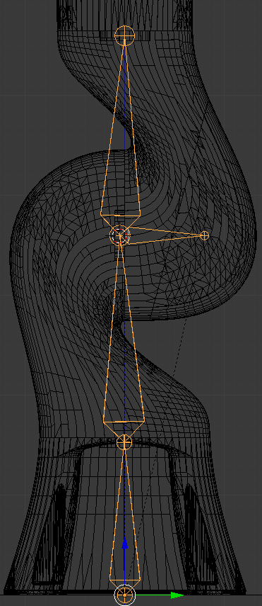
This rig is quite simple, actually. It is a single chain of bones for deformation with a few miscellaneous bones for animation control. This answer is a walkthrough of my process in creating the rig. For a point of reference, a rig is a series of bones built to deform a mesh for animation.
Rig the mesh using Inverse Kinematics (IK). IK allows the bone at the end of the chain to be manipulated directly. Positioning the end bone causes each bone between it and the top of the chain to be repositioned automatically. This contrasts with FK (Forward Kinematics) where you position each bone in sequence from the top of the chain to the bottom.
Solution
In the proposed solution there are a few items to note: (1) the head of the robotic arm is named sphere; (2) the topmost bone is named tip; (3) the target bone is named ik-target; and (4) the armature is called ik. Then:
- Create and align bones with the mesh so that rotation is restricted to one axis.
- Add an IK constraint to
tip.
- Create (duplicate??) the
ik-target bone from tip.
- Parent
- Give
sphere a target of ik-target.
- Ensure
ik-target is parented under ik.
Then I started locking the bone axes I can't use. These are the axes that rotate in a direction that would break the mesh joints. These were either the X or Y axis, depending on the bone. Take note of the axis I locked and notice which direction it is supposed to rotate in. I did this in the bone properties, under the IK section:

This keeps the IK solver from using these axes when it calculates the position of the middle bones. For easier axis management, I changed the rotation method of all the bones to XYZ Euler instead of Quaternions. Eulers are suitable in this scenario because of the single-axis nature of a robot.
Lastly, add a copy rotation constraint on tip with a target of ik in World Space. This enables intuitive rotation of sphere while maintaining the translation.
This rig is simple and must be expanded to get every function available in the robot. Animating the head will need another bone hierarchy. There is a special case where the robot rotates the head around the tip of the probe. This will require another rig layer.
Feel free to use my rig if you wish.
Notes
There are two rigs, one on each layer. The first layer is an FK chain, which is fairly simple and only uses a parent hierarchy to move the mesh. The second is the IK rig, which I described above. I was going to recommend using the FK rig because of its simplicity, but the functions you want are fairly complex to animate in an FK chain.
Example Blend File
Pick apart the sample file to get started:


