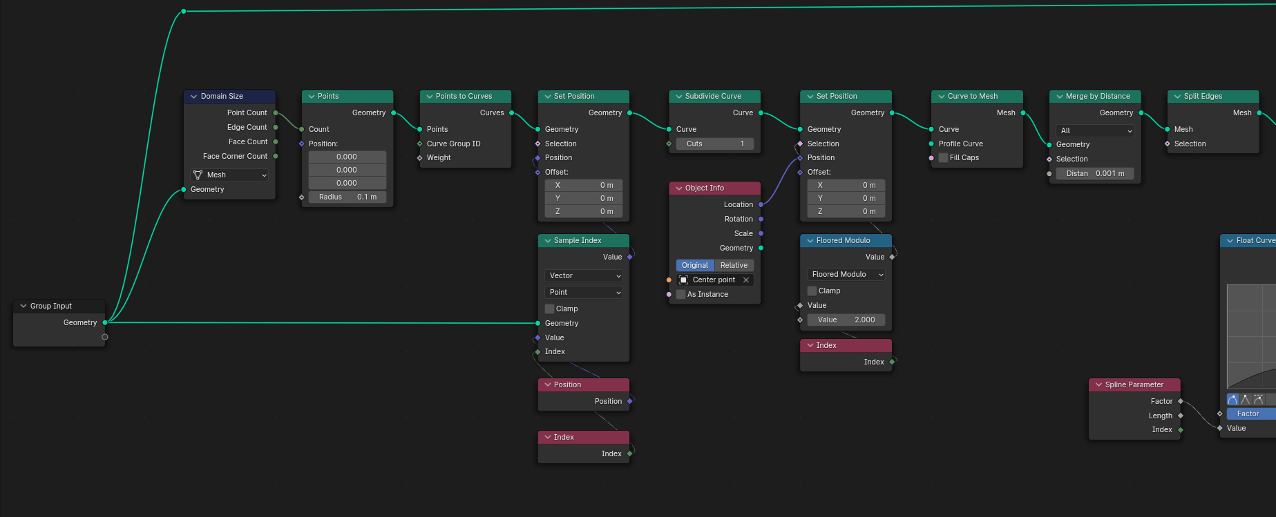
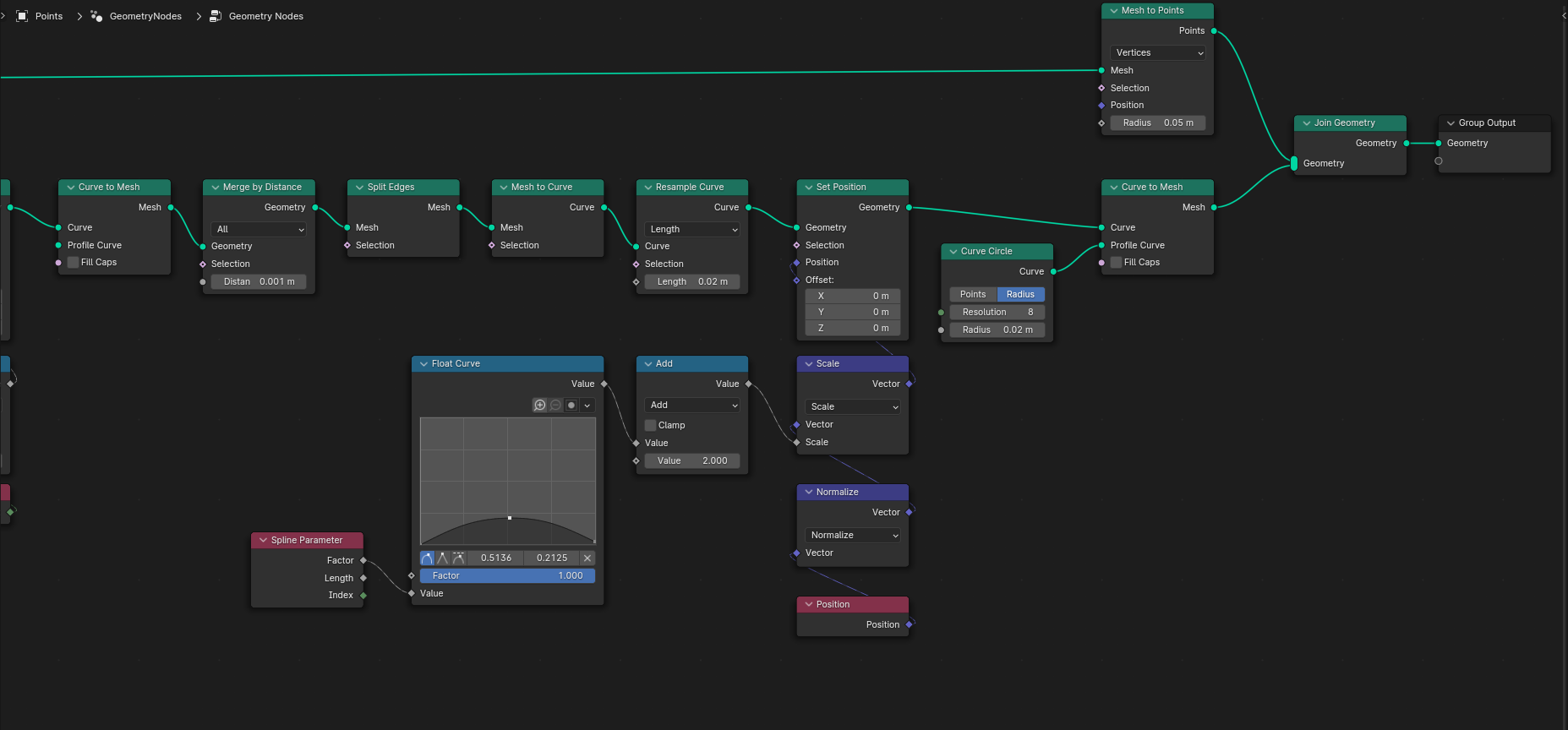
(Using Blender 3.6.5 and Geometry Nodes)
NB: This answer is under work and has yet to be fully documented...
Objective
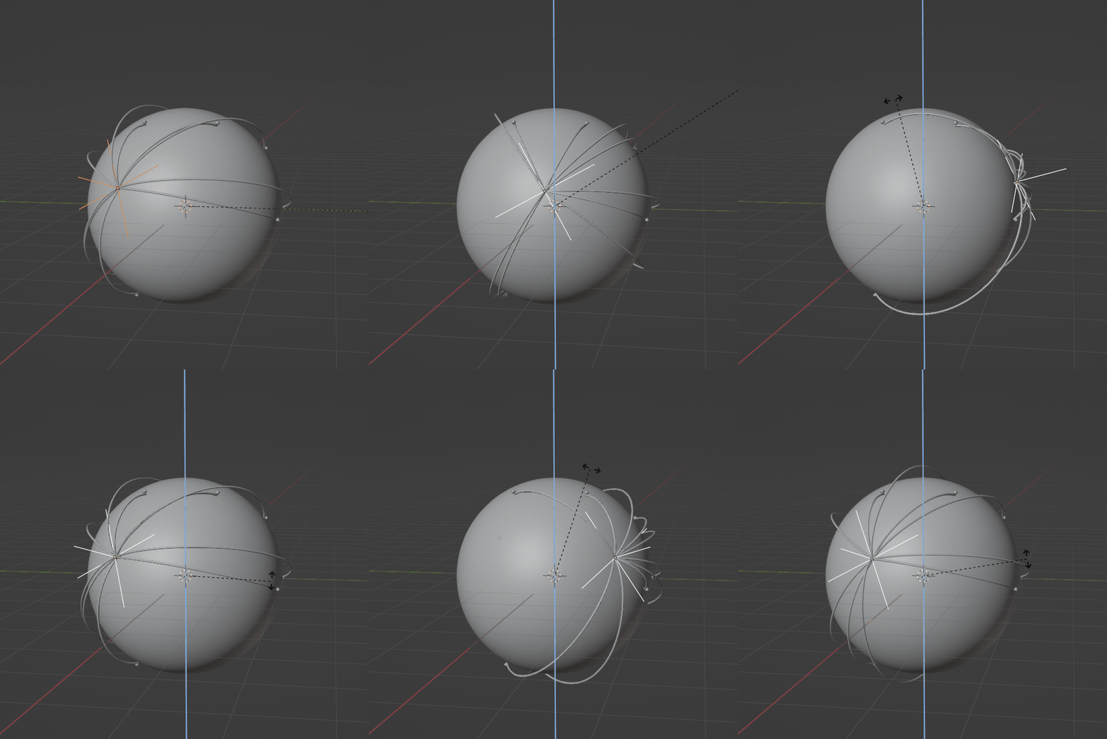
Build Bezier curves connecting pairs of points on a sphere, controlling mid-point height.
Approach
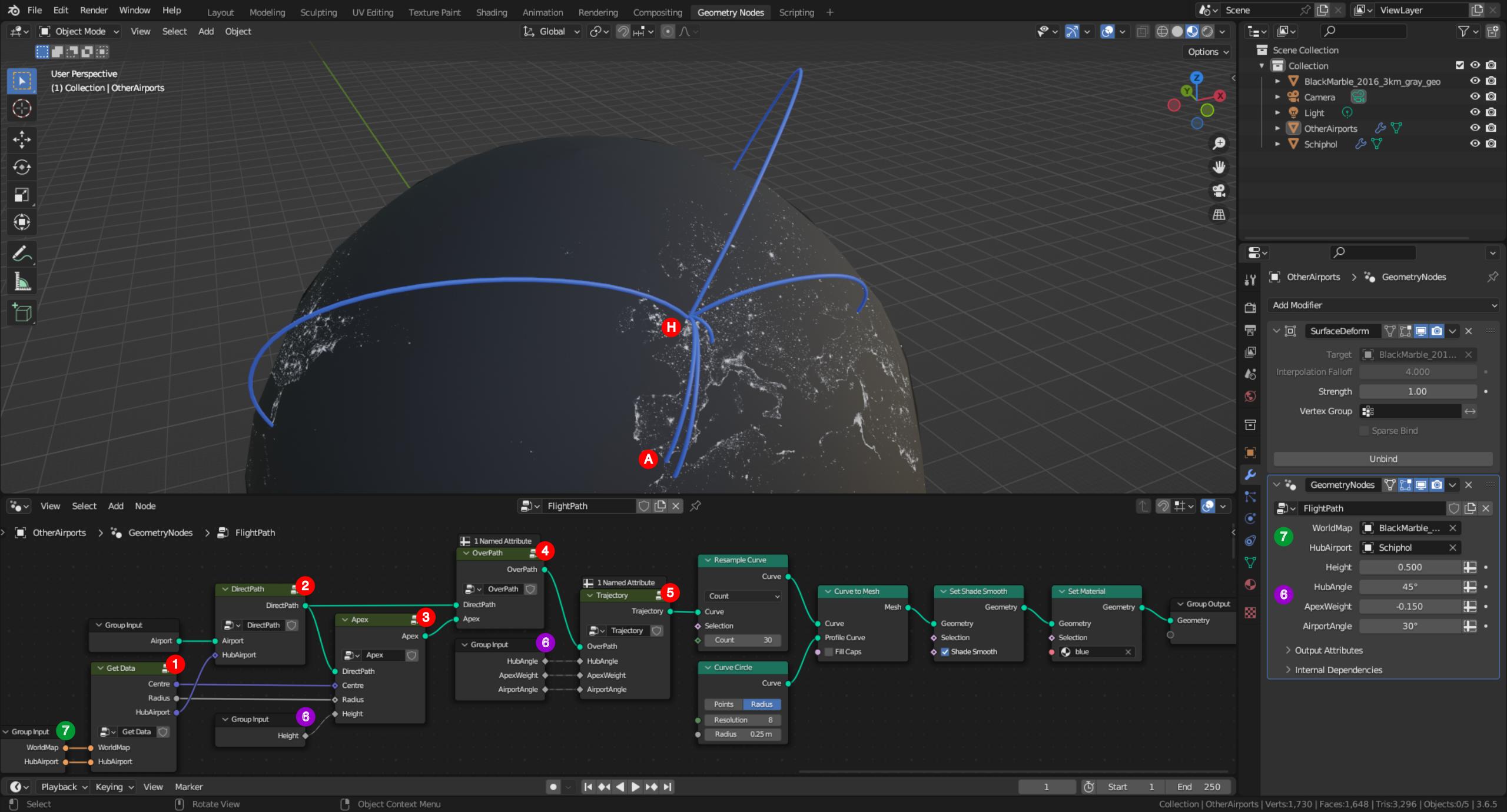
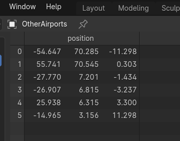
The GeometryNodes modifier is added to the object made of vertices put at the targetted airports position (named OtherAirports in the demo file).
1. Sphere properties and hub airport (named Schiphol in the demo file) position are recovered from objects specified through the Group Input node (label 7).
2. A single edge per targetted airport (label A) is build to connect it to the hub airport (label H).
3. The perpendicular bisector to those edges crossing the sphere centre is used to shift outward the mid-point. These points are collected as a point cloud.
4. Edges and apex points are combined in broken lines made of three points and two edges.
5. These pairs of segments are converted to Bezier curves, which handles are modified to tune the flightpath shape.
6. Control parameters are:
6.1. Height: Fraction of the circular arc connecting H to A used to shift the apex. A value of 0 puts apices on sphere.
6.2. HubAngle: Additional angle between the curve tangent and the edge connecting H to apex. Positive values increase "take-off" slope.
6.3. ApexWeight: Factor controlling the radius of curvature at apex. 0 is the default value. -1 makes a sharp angle. Positive values yield flatter curves.
6.4. AirportAngle: Additional angle between the curve tangent and the edge connecting apex to A. Positive values increase "landing" slope.
Process data
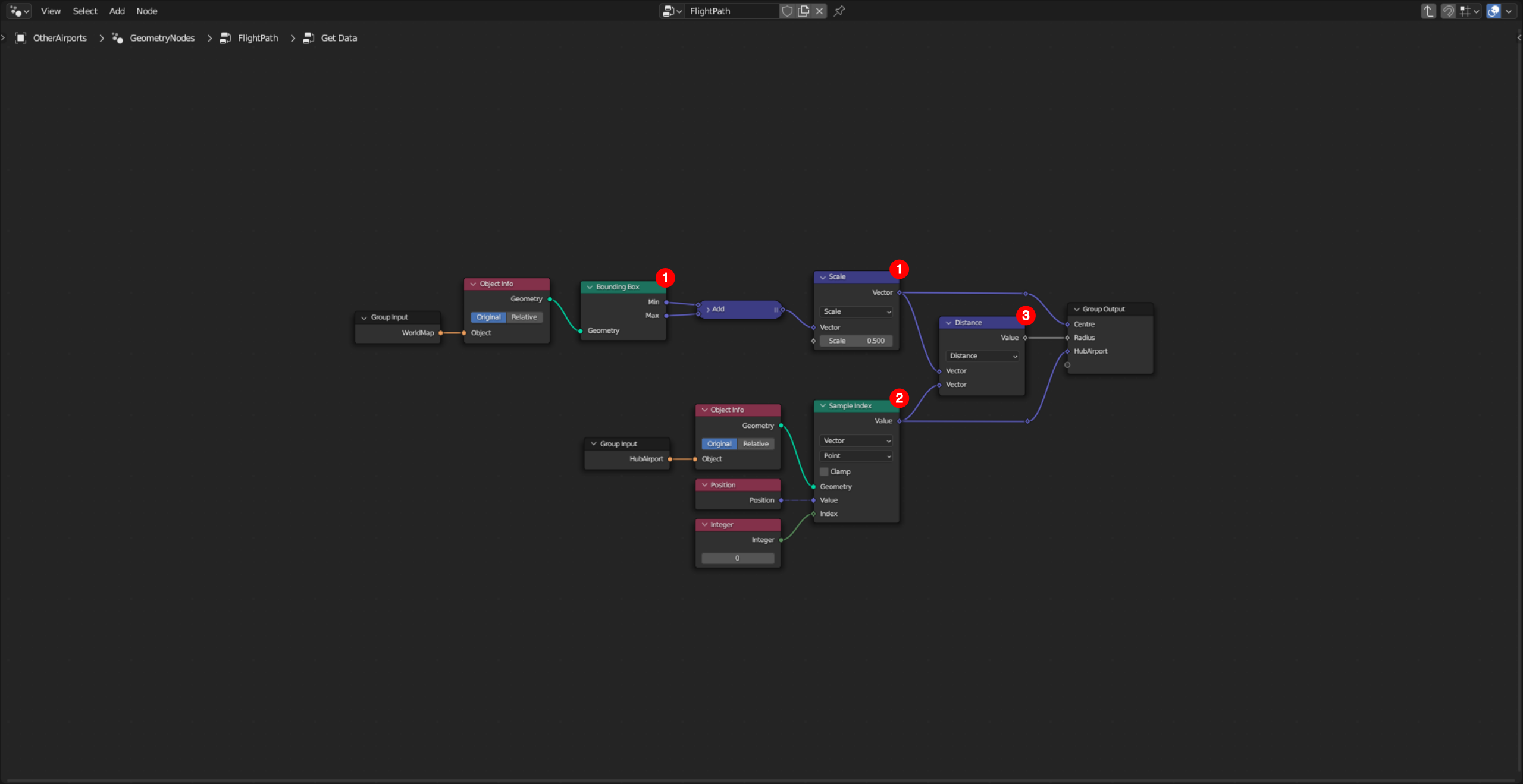
1. The centre of the sphere (labelled C) is computed as the middle of its bounding box.
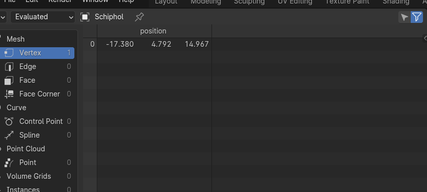
2. The hub airport position (labelled H) is recovered with a Sample Index node set in Point domain. It is assumed that the hub is at Index 0. This procedure is robust if there is more than one vertex in the input object, and if the vertex is moved from the origin.
3. The sphere radius is computed as the distance between points C and H.
Build direct paths
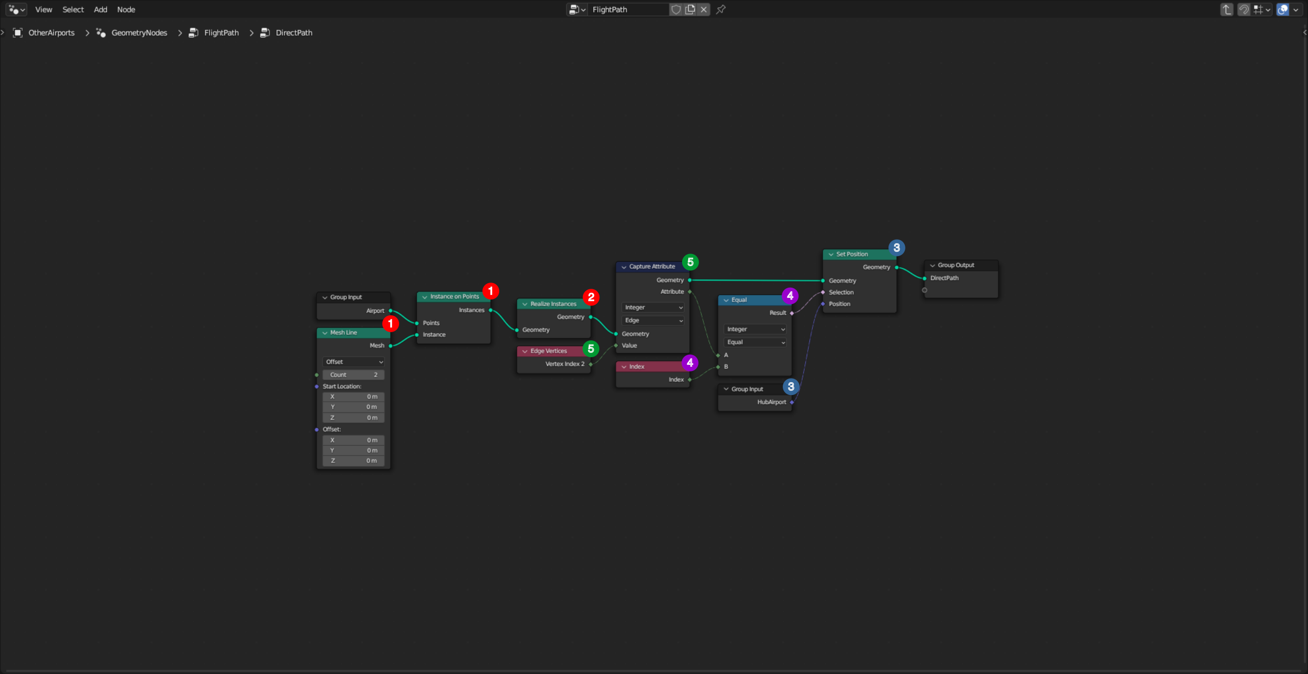
Direct paths are segments connecting the targetted airports (labelled A) to the hub airport (labelled H).
1. Using an Instance on Points node, a single edge is put at every vertex A of the Airport mesh provided by the Group Input node. As the Mesh Line Start Location is (0,0,0), the position of the Index 1 vertex of an edge (labelled V1) is equal to the position of the associated point A. The Offset parameter is irrelevant, as the position of the Index 2 vertex (labelled V2) will be edited afterwards.
2. Through a Realize Instances node, instances are made independent edges.
3. The position of the vertex V2 of every edge is set equal to the position of point H, provided by the Group Input node.
4. Because it is downstream the Realize Instances node, the Set Position node modifies the Point domain. So the Index tested to define the Selection mask is a Point index, not an Instance index.
5. Through a Capture Attribute node set in Edge domain, the index of vertex V2 is recovered to be compared to the actual point Index. Its value is provided by an Edge Vertices node.
Compute apices
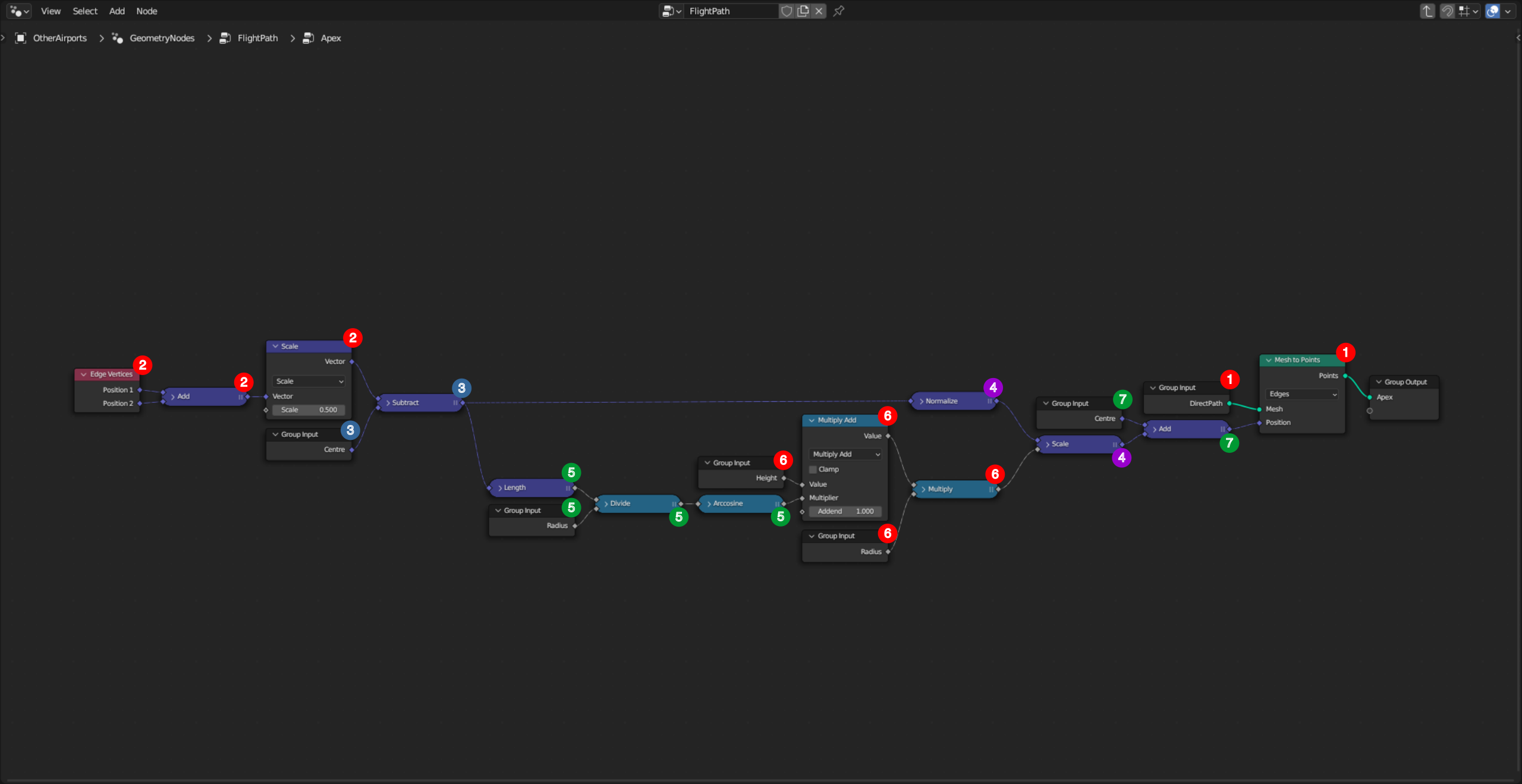
Apex is the highest point of a flightpath.
1. A point per direct path edge is created using a Mesh to Points node set in Edges domain. The procedure to compute its position follows. These points are collected in a Point Cloud. It is to notice that an edge and the associated point are sharing the same Index, but in different domains.
2. The mid-point position of an edge [AH] (labelled I) is computed from its two end vertices, which position is recovered with an Edge Vertices node.
3. The perpendicular bisector of [AH] is computed by subtracting the sphere centre position (labelled C) to the mid-point I position, because points A and H are laying on the sphere. So $\vec{CI}$ is perpendicular to $\vec{AH}$.
4. This vector is normalized to be scaled afterwards by the apex height. This height is a function of the length of the circular arc connecting A and H. Let $\Delta \theta$ be the angle between $\vec{CI}$ and $\vec{CH}$, and $R$ the sphere radius. The length of this arc is then $2 R \Delta \theta$.
5. $\Delta \theta$ is such that $\cos{(\Delta \theta)} = \|\vec{CI}\|/R$.
6. The distance between point C and the apex is defined as $(\kappa \Delta \theta + 1) \times R$. The $\kappa$ parameter is user-defined, and its value is recovered through the Group Input node. For $\kappa=0$, the apex is on the sphere ; for $\kappa=2$, the apex height is equal to the distance between A and H along the sphere.
7. The apex position is defined from point C, by adding the vector computed at step 4. So by construction, points C, A, H and the apex are coplanar.
Build over paths
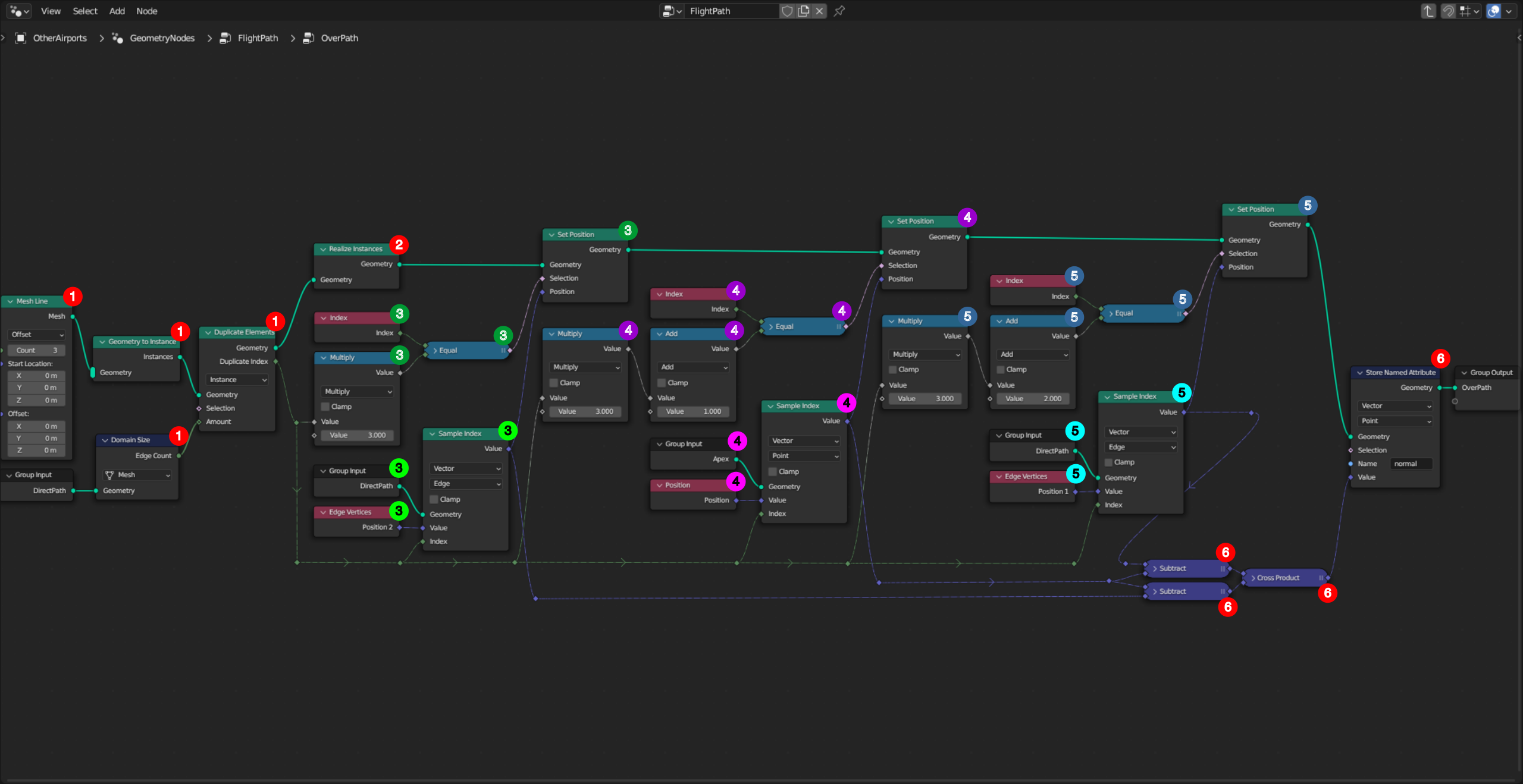
Over paths are made by combining direct paths end points and apices in sets of two edges.
1. A Mesh Line with two edges sharing one central vertex is duplicated as many times as the number of direct paths. Start Location and Offset parameters are irrelevant, as vertices position will be set afterwards. It is to notice that the Duplicate Elements node is set in Instance domain. This way, duplicated edges remain connected. Whereas in Edge domain, this connection is lost as two vertices are created at the junction. So the three vertices of copy number $i$ are with indexes $3i$, $3i+1$ and $3i+2$.
2. Through a Realize Instances node, instances are made independent sets of edges. Subsequent Set position nodes are thus in Point domain.
3. Point H is copied as the first vertex of the $i^\mathrm{th}$ copy.
3.1. Its index matches the selection mask $3i$.
3.2. Point H position is recovered with a Sample Index node set in Edge domain, looking for the $i^\mathrm{th}$ direct path. As point H was recorded at second position by the DirectPath node group, its coordinates are provided by the socket Position 2 of the connected Edge Vertices node.
4. The apex (labelled T) is copied as the second vertex of the $i^\mathrm{th}$ copy.
4.1. Its index matches the selection mask $3i+1$.
4.2. Point T position is recovered with a Sample Index node set in Point domain, looking for the $i^\mathrm{th}$ apex.
5. Point A is copied as the third and last vertex of the $i^\mathrm{th}$ copy.
5.1. Its index matches the selection mask $3i+2$.
5.2. Its position is recovered as for point H, but from the socket Position 1.
6. The normal to the plane defined by (H,T,A) is computed as $\vec{TA} \wedge \vec{HT}$. It is stored in an attribute named normal, to be used to rotate the Bezier curves handles.
Build and adjust flightpaths
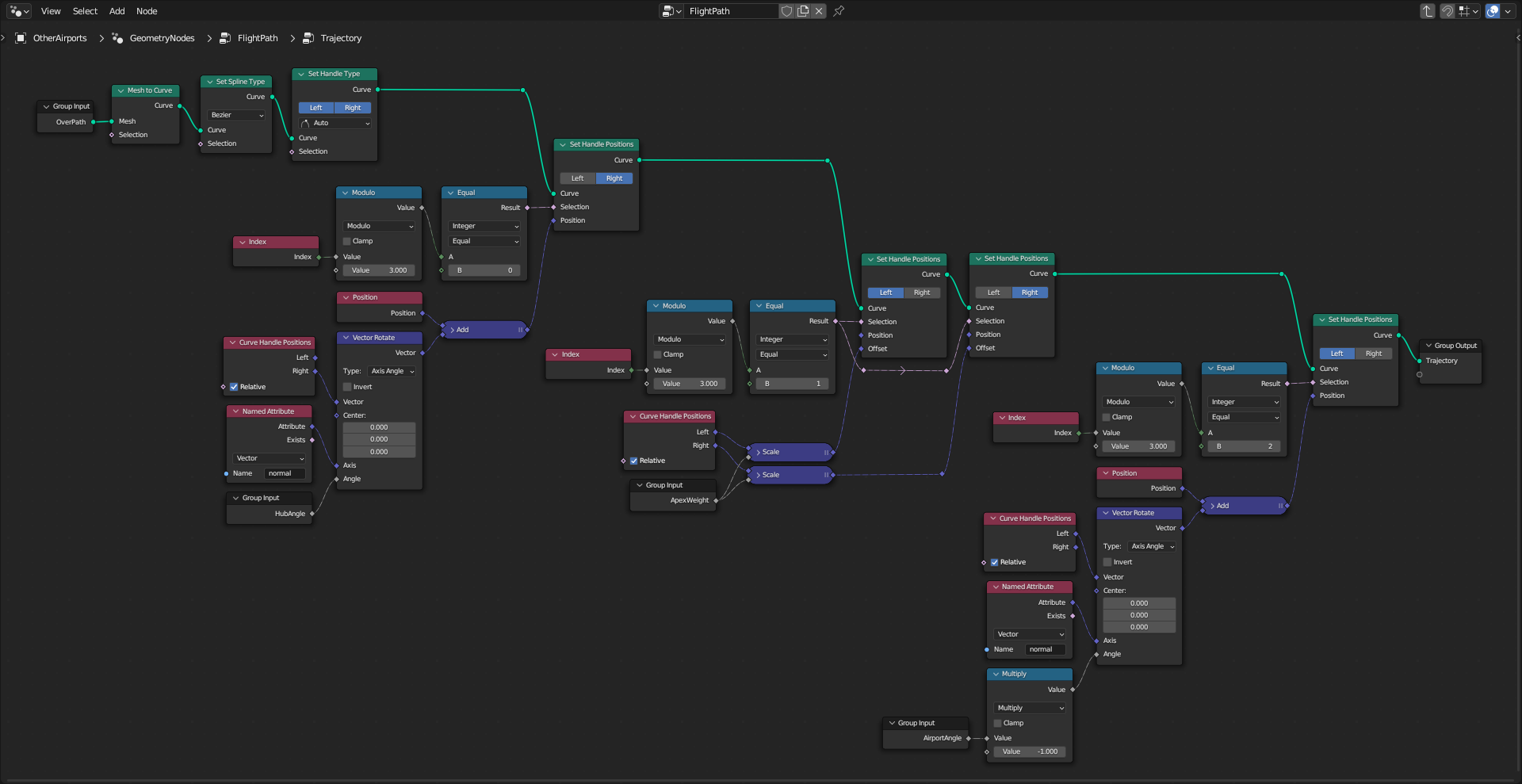
1. .
2. .
3. .
Resources


