3
$\begingroup$

I have created these two elements (as individual objects):
Objects meant for instancing

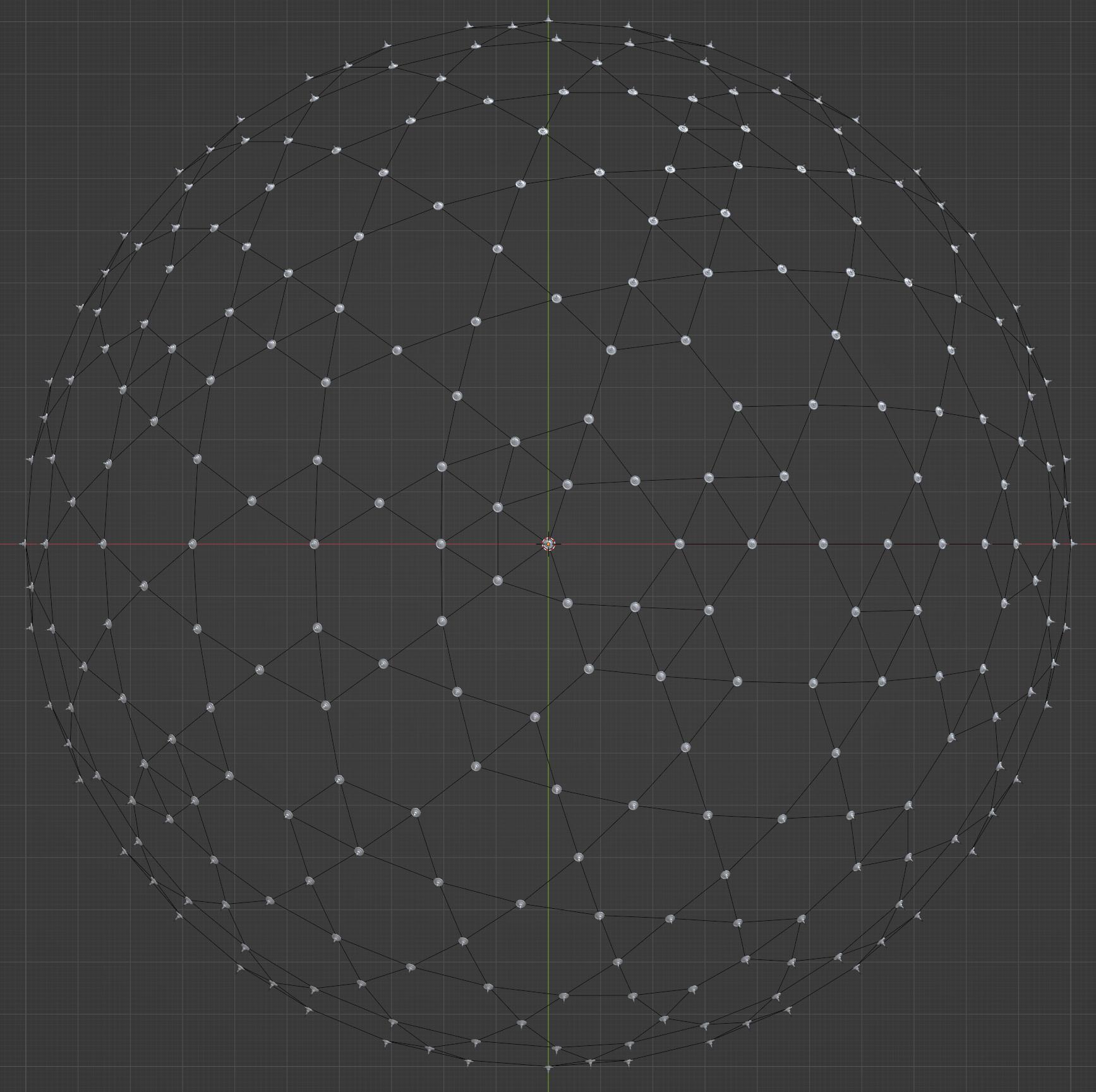
I have also created an Icosphere (and modified it a bit) to use as a guide/lattice for structure.

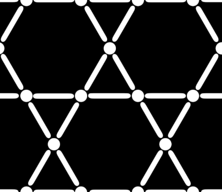
I would like to create a Geometry Nodes thing that instances the "circular" object on the vertices of the lattice mesh (I've accomplished this part) and also instances the "long" object along the edges of the lattice mesh, to basically come up with this kind of look (but on the surface of the 3D Icosphere):
The Goal

Here's what I have so far. You can see that I've instanced the circular object on the vertices of the Icosphere, as I wanted. But I can't figure out a good way of instancing the "long" mesh so that it goes along each of the edges:
Terminators instanced on points/vertices

How could I go about doing that? Also to mention: Not all edges are the same length, so it would need to scale with the length of the edge as well.

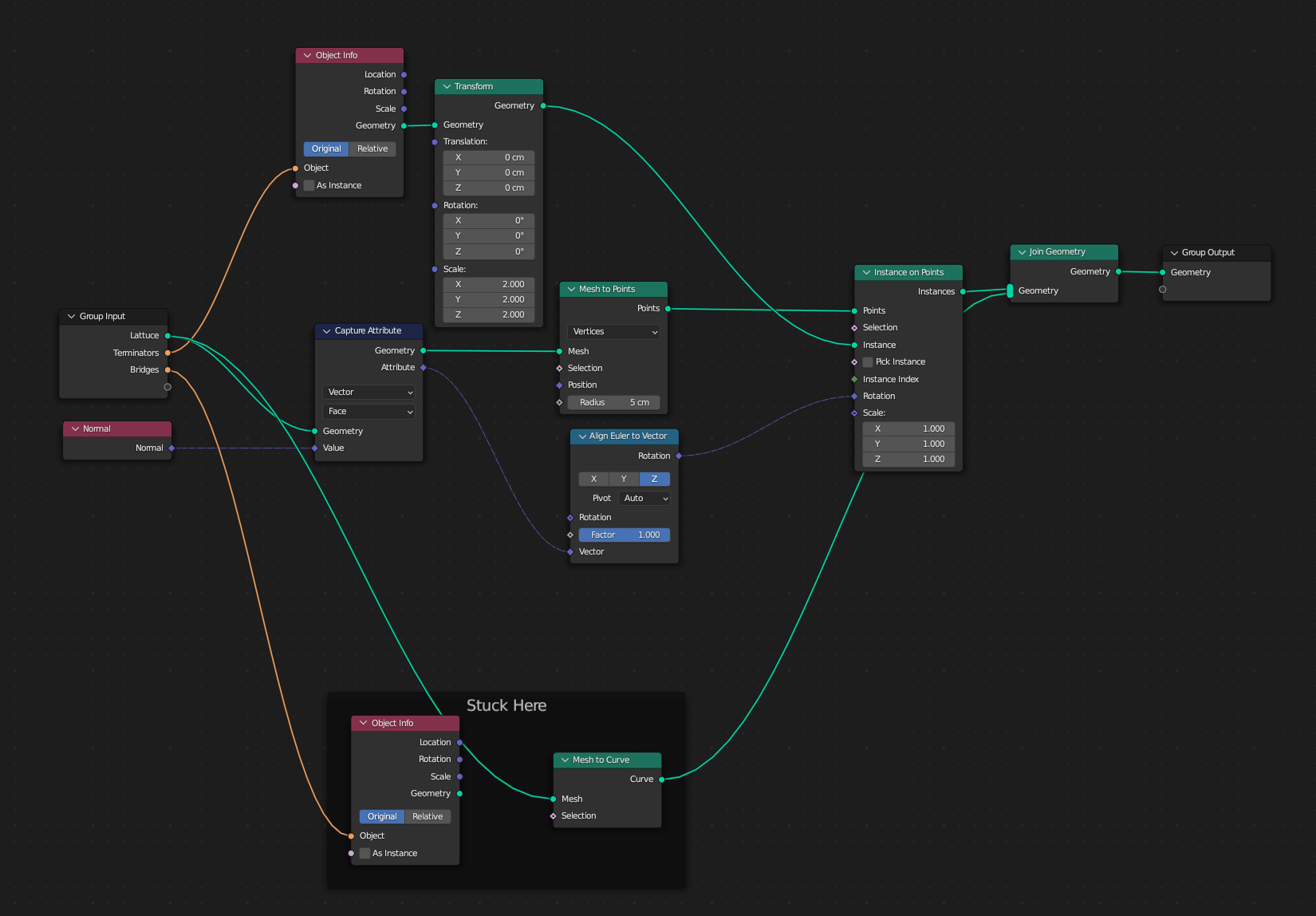
Here is what I have in Geometry Nodes so far, although this is just instantiation on points:
Geo Nodes so far

$\endgroup$
7
  • $\begingroup$ Hi Michael - i recommend providing a blend file so people don't have to rebuild everything manually on their own. By that you will attract more people to your question. $\endgroup$
    – Chris
    Commented Jul 7, 2023 at 5:26
  • $\begingroup$ Thanks -- I haven't really done anything that needs to be recreated though. My question is about how to even get started on it. $\endgroup$
    – Michael
    Commented Jul 7, 2023 at 5:58
  • $\begingroup$ i meant just the node tree you showed us in your image - nothing more $\endgroup$
    – Chris
    Commented Jul 7, 2023 at 6:21
  • $\begingroup$ Hello and welcome to Blender.SE! Have you tried using Mesh to Points (set to Edge)? $\endgroup$
    – quellenform
    Commented Jul 7, 2023 at 6:52
  • $\begingroup$ Hi, @quellenform! ... for generality, does one problem remain, after that? How to stretch truss-instances on edges to length, without distorting semicircular caps? $\endgroup$
    – Robin Betts
    Commented Jul 7, 2023 at 8:00

1 Answer 1

6
$\begingroup$

I'm not sure I understood you correctly, but obviously you want to instantiate two different meshes at the points of another mesh. Like this:
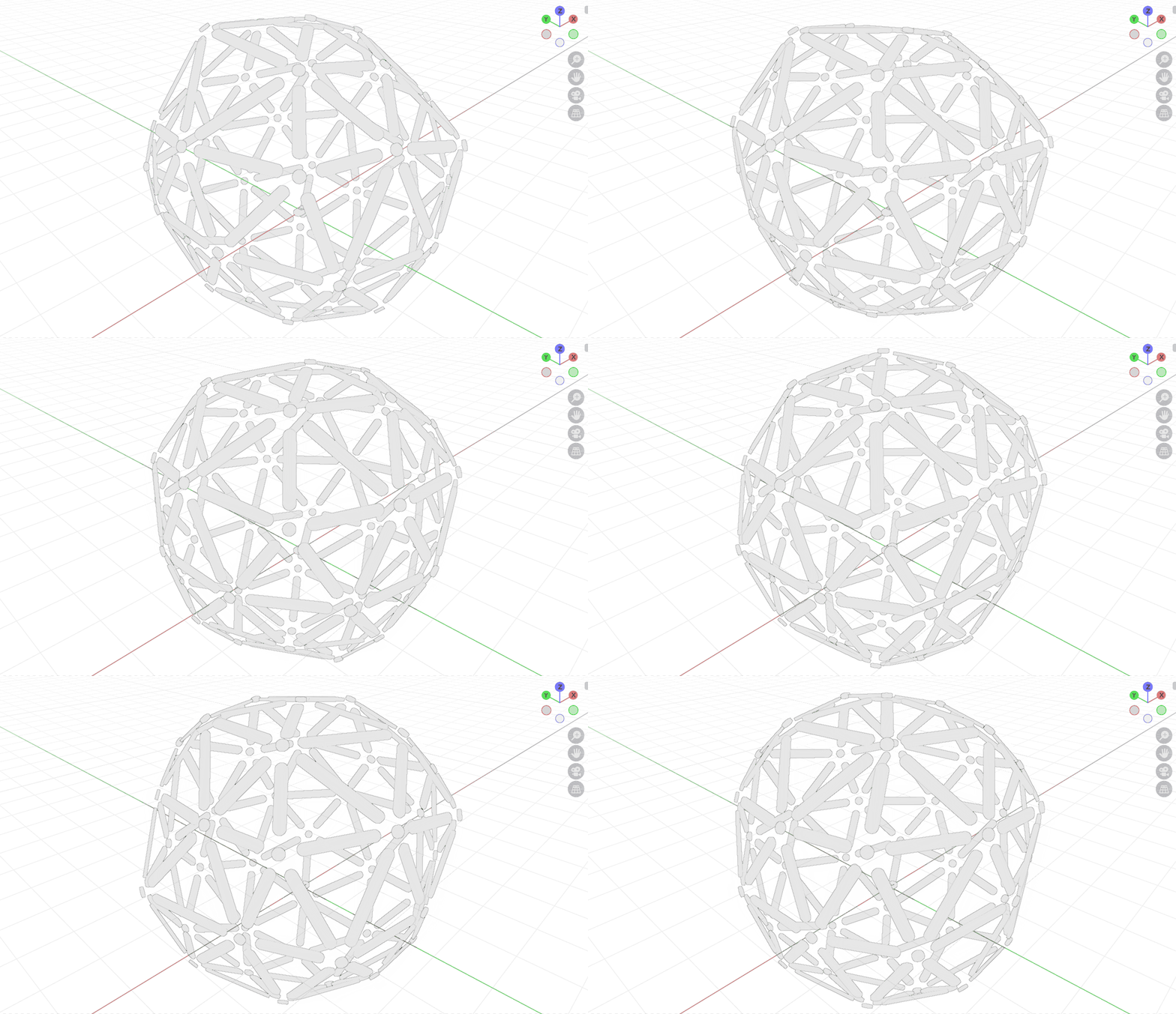
enter image description here

The following is what you want to achieve:

  • At the points of the mesh, one shape is to be instantiated.
  • In the center of the edges the other shape should be instantiated, stretching it to the length of the edge.

Therefore I assume the following two simplified shapes in my example:
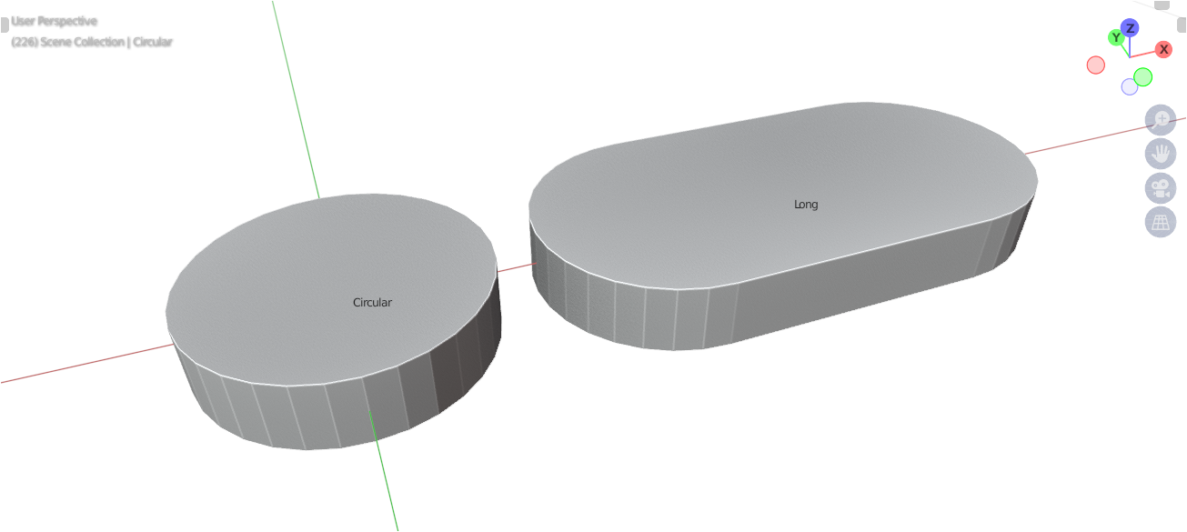
enter image description here

Instantiating the circular shape at the vertices is easy, but the edges are a little trickier here.

You could, of course, just scale the mesh, but that didn't seem to me to be particularly helpful in this case, because that would cause the mesh itself to lose its actual shape.

In your example, however, you show a mesh that could be split down the middle, and all the points that lie on the X-axis in the positive range could be moved to the right, and all those that lie in the negative range further to the left. This would minimize the deformation or keep the original idea of the shape.

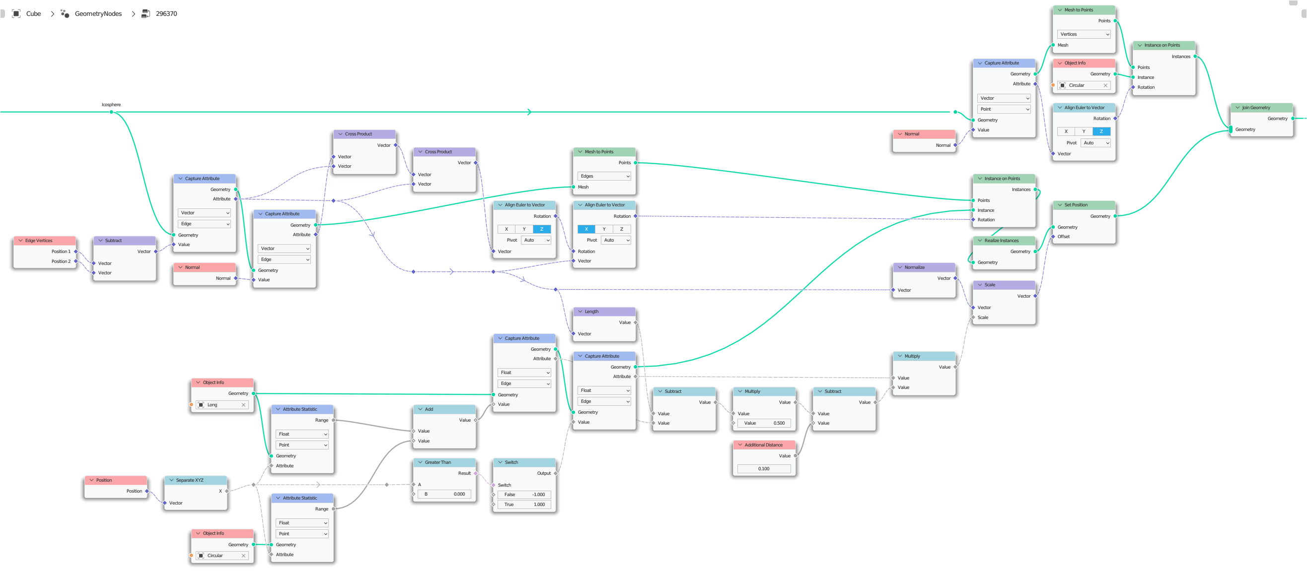
So this task can be solved something like this:
enter image description here

Here I first capture the normals of the edges, and the vector between two endpoints of an edge (the direction of the edge). Since the normals of the edges can behave strangely when the underlying mesh is deformed, I use a trick here with the cross product so that I can reliably get the upvector for aligning the objects.

You can find countless variations of how to align objects along an edge or a normal here on this platform, in case the illustration isn't entirely clear to you.

Stretching the object or moving the points along the edge direction to the length of the edge is a bit more extensive.

As mentioned before, here I move the points depending on their X-position to the left or to the right along the direction vector of the edge.

For this you need additionally on the one hand the information about the length of your object, and on the other hand of course the information about the length of each edge.

By subtracting the length of the object from the length of the edge, dividing this value and multiplying it by $-1$ or $+1$ (left or right), you get a value that you can use to scale the direction vector of an edge and finally as an offset to move the individual points of your objects previously instantiated at the centers of the edges.

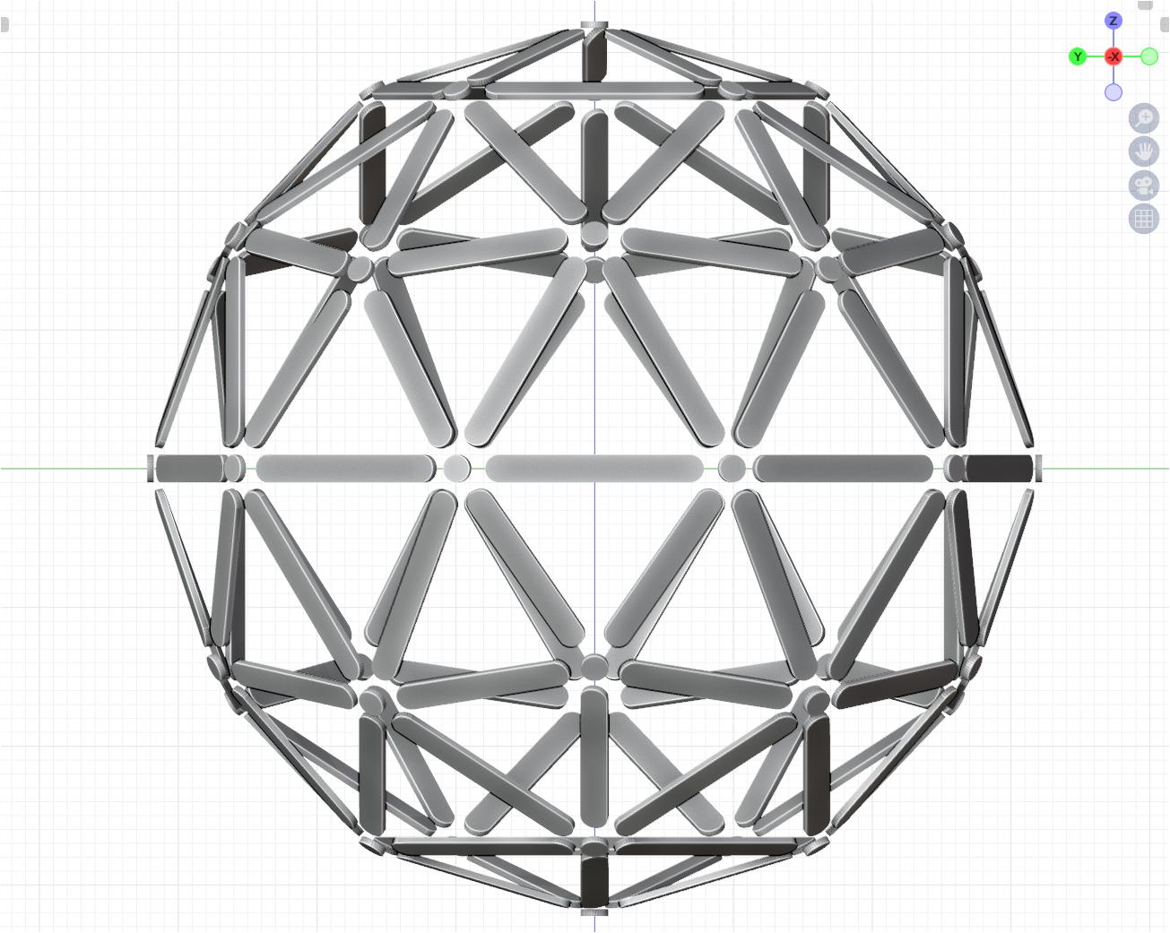
If you apply this to your mesh, it looks something like this:
enter image description here

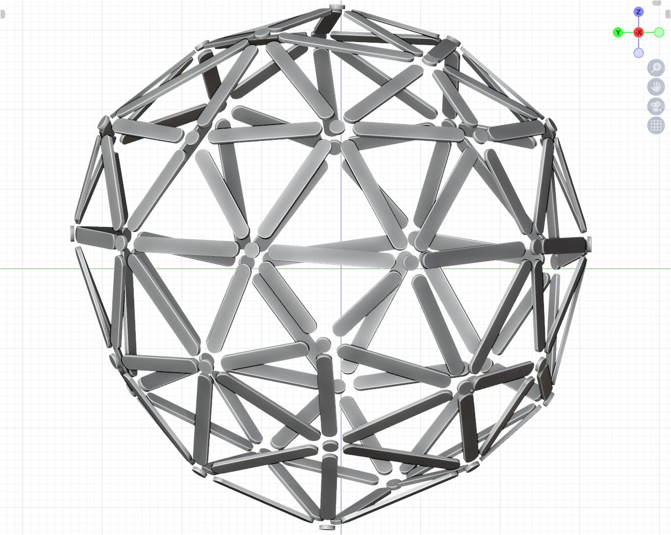
And if you warp the mesh (for example, as I did here in this example) so that you get edges of different lengths, then it looks like this:
enter image description here


(Blender 3.4+)

$\endgroup$
2
  • 1
    $\begingroup$ This is the reason I held off :) .... Neater than mine. by quite a few nodes! I guess I exposed a few adjustments.. but they belonged outside the tree. $\endgroup$
    – Robin Betts
    Commented Jul 7, 2023 at 11:56
  • $\begingroup$ Wow! I struggled to even ask my question, and you answered it so eloquently. Thank you, this is above and beyond what I was hoping for (especially widening the long parts -- I didn't even bother to ask for that!). Thank you so much; this works perfectly and gives me a ton of information to study as well! $\endgroup$
    – Michael
    Commented Jul 8, 2023 at 3:02

You must log in to answer this question.

Not the answer you're looking for? Browse other questions tagged .