4
$\begingroup$

enter image description here

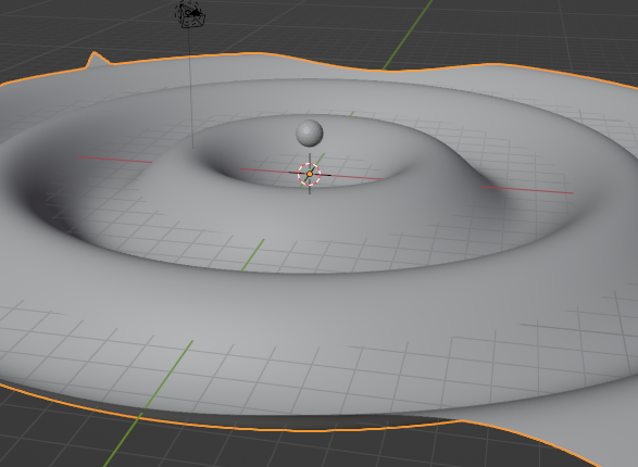
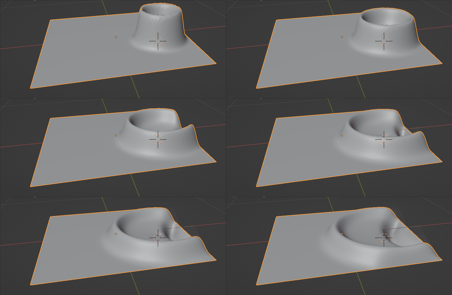
I would like to have these waves ripple away from the sphere while only changing near the sphere and propagating out. At the moment I can move the sphere but they all update simultaneously

Edit: With the new simulation nodes this should be possible. I'm trying to come up with some kind of logic to make this happen.

Edit2: It's not easy. I tried to make it so that the change in speed of an object increases the displacement but the waves always grow. Dunno how to "reset" back to it's original position.

$\endgroup$
5
  • 1
    $\begingroup$ Geometry Nodes are not iterative, though there are hacks to make them so. I haven't yet tried with dynamic paint... $\endgroup$ Commented Oct 6, 2022 at 20:51
  • $\begingroup$ Also related: How to create a simulation in Geometry Nodes? $\endgroup$ Commented Dec 1, 2022 at 14:49
  • $\begingroup$ yep, i agree, with the new simulation nodes this IS possible $\endgroup$
    – Chris
    Commented Dec 3, 2022 at 8:03
  • $\begingroup$ maybe share your blend file with what you already have? $\endgroup$
    – Chris
    Commented Dec 4, 2022 at 9:09
  • 1
    $\begingroup$ @Chris I've figured out how to do it using Markus' approach as inspiration. The waves only appear when the object moves and the speed affects the size of the waves. I'll post an update this evening. Haven't found a good way of transferring that to a mesh surface. As it's very "pointy" if I use distance methods. $\endgroup$
    – TheJeran
    Commented Dec 5, 2022 at 12:22

3 Answers 3

7
$\begingroup$

Yes - this is now possible with the new Simulation functionality being developed in Geometry Nodes :
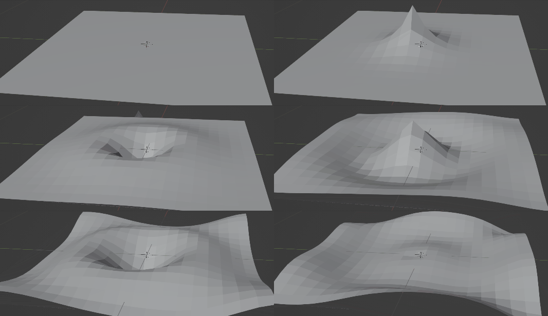
final result

This can be achieved with the new 'Simulation' functionality of Geometry Nodes - where the state from a previous frame can be used to build the current frame using nodes. Note that the functionality is only currently available in the latest Alpha daily build in an "experimental" branch of Blender (https://builder.blender.org/download/experimental/ - see "Blender 3.5.0 - geometry-nodes-simulation") and is subject to change and/or may not make it into the standard build of Blender.

The Simulation Nodes extension provided additional "Simulation Input" and "Simulation Output" nodes - anything within the two nodes will be used to calculate the changes when changing animation frame.

So, in order to animate a mesh in this way we need a number of things :

  • We need to be able to displace part of the mesh - either by proximity to another mesh/object or mathematically (eg, as a Sine wave)
  • Each point in the mesh needs to have a Velocity and effective mass (we'll assume the same mass for every point and so don't need to store it). This allows it to continue moving and have an energy that can propogate through the mesh.
  • Each point needs to be affected by the displacement of its neighbors.
  • Each point will be locked in position except for its Z position (so it can only move up and down)
  • We need to calculate the new position and velocity each frame.

We need to store the velocity for each point in the mesh and we can do this with a Named Attribute.

store an initial velocity of zero

We can then add the displacement. I've opted to do this mathematically, but it should be possible to base this on proximity to another mesh (just more complicated). I used a Set Position node to set the Z coordinate based on a Sine wave that can be animated. Note that I've set which point to animate by calculating the index based on the known dimensions of the Grid (in my case 21x21 grid so the centre point (row 11, column 11) is "21*(11-1) + (11-1)" = 220).
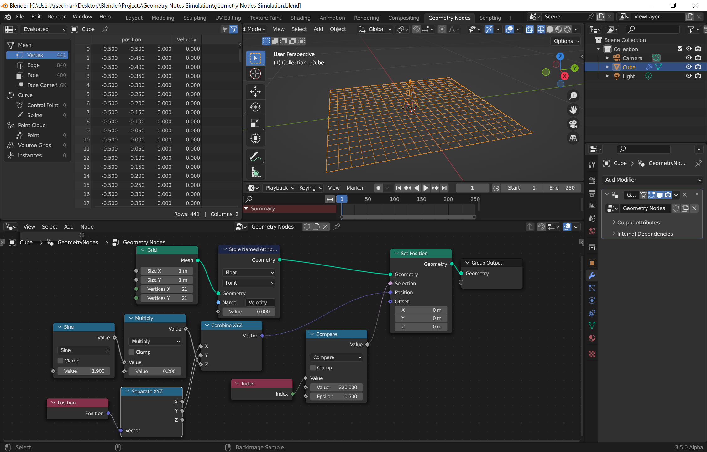
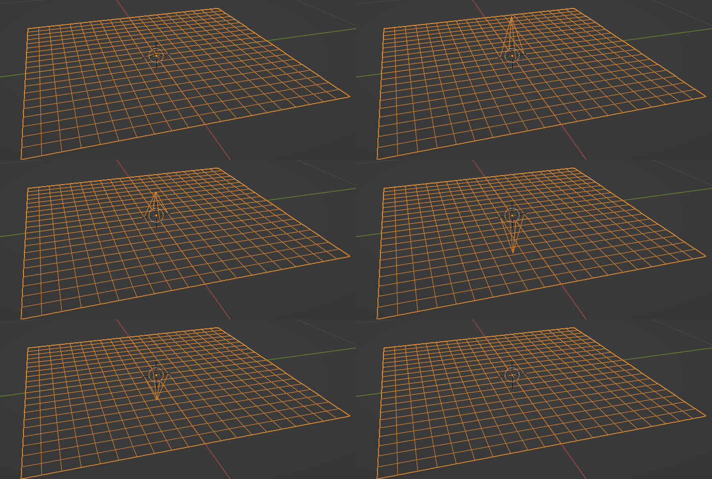
displace vertex by Sine wave

animated image of moving vertex

Calculating the displacement from its neighbors is a bit more tricky since we need to know which vertices it's connected to and their position. This isn't easy to do, but one way is via the Edges of Vertex node. This retrieves the Edges that are connected to the vertex with an index that can be used to select each edge.

Unfortunately there isn't a simple way to retrieve the actual vertex position of the neighbor but we can retrieve the Position of the edge which will be half-way between the current Vertex position and the neighbor's position.
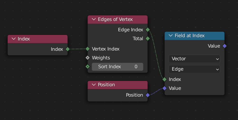
getting an edge midpoint

Summing the (up to) 4 vertices and dividing by 2 will give us the average displacement (since there are 4 vertices and the displacement is only half as far due to being the midpoint of the edge). Note that the Sort Index is incremented to select the edge being sampled.
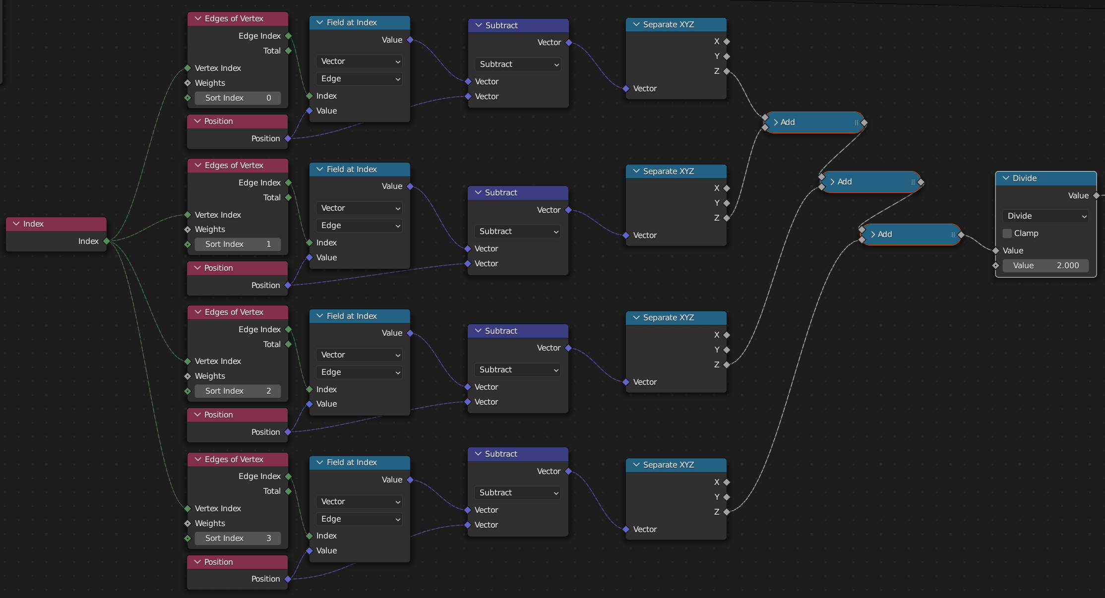
averaging the displacement of neighbours

The output of the above can now be used to adjust the stored Velocity of each verted - by retrieving the current velocity, adding in the new 'pull' of the surrounding vertices, and then storing the Velocity again. In addition, the new velocity can be used as a Z-offset to the current Position of the vertex.
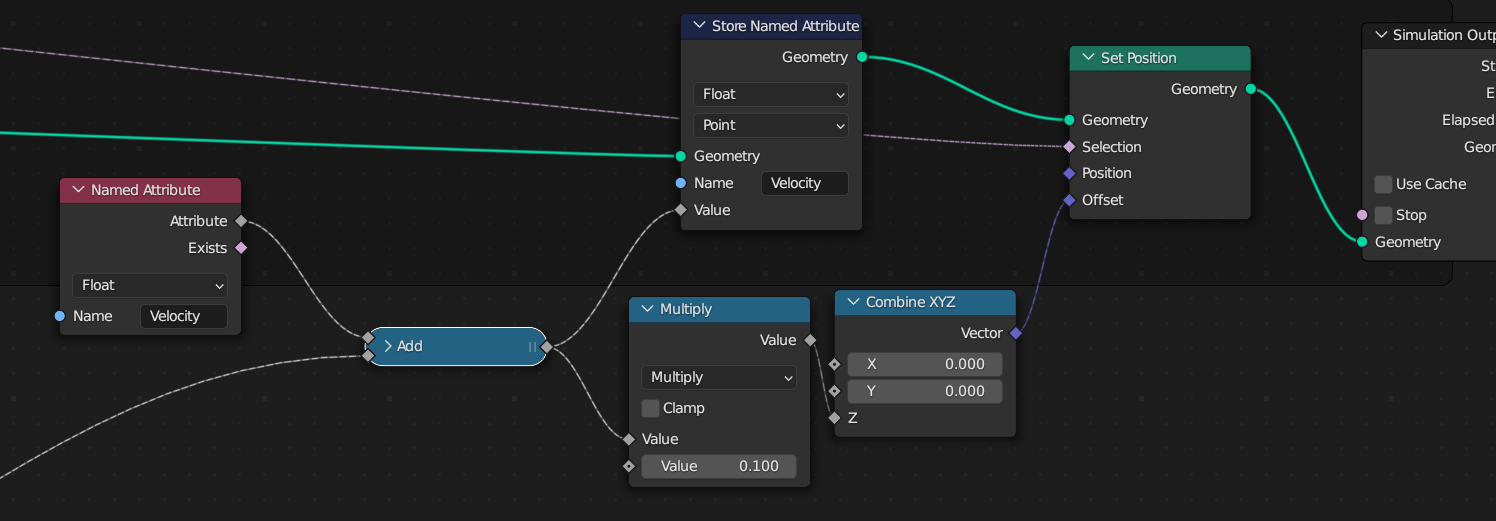
velocity update and position offset

The new Simulation Input/Output nodes are used to surround the nodes that need to be evaluated on each frame - so the displacement of a vertex and the calculation and application of the velocity. This gives something like the following node structure :

full node tree

You can add some damping to the motion by adding a Multiply node before storing the new Velocity - eg, to multiply by 0.99 to damp the velocity by 1% each step. This will calm the motion over time. Here's the final result with increased grid resolution :
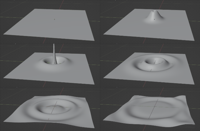
final result - higher res

Blend file included (but requires Blender 3.5.0 Alpha (or later) Geometry Nodes Simulation build


EDIT : Just to prove that it's possible to affect this based on mesh proximity, here's a bit of a dirty hack to the nodes to use the position of another mesh (animated to collide with the surface) to affect the velocity of the grid :
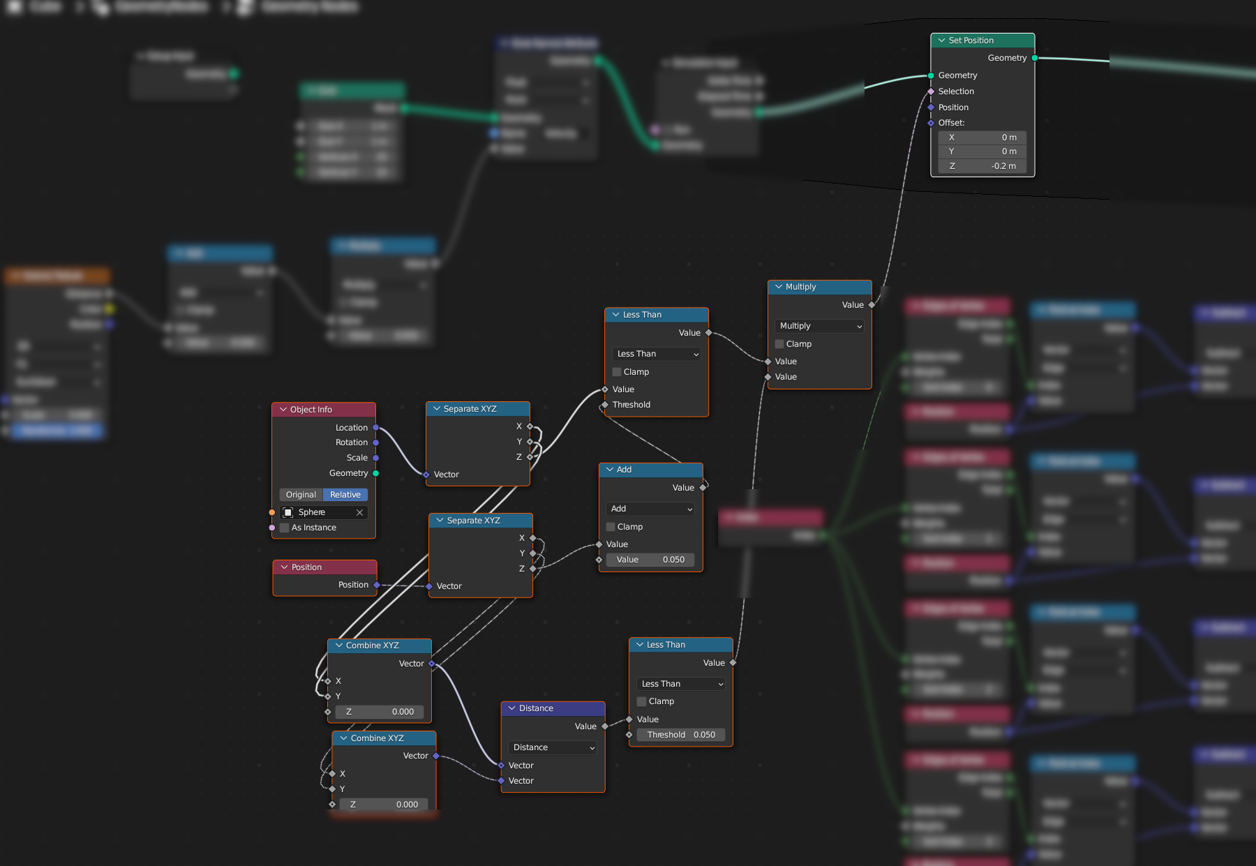
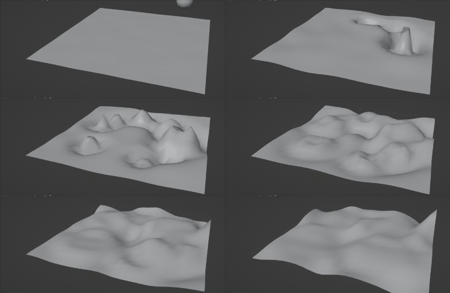
mesh proximity hack

final mesh proximity


EDIT: From Robin Betts suggestion as to reflections, it's relatively easy to add a 'hard edge' to the grid where the vertexes are fixed - and this results in reflections from the boundary. This can be achieved by using the Total output of the Edges of Vertices node - as this will be 4 for any vertex in the bulk of the grid and less than 4 for any edge or corner vertex (which will be missing one or more neighbours) - see the selected nodes in the following image :
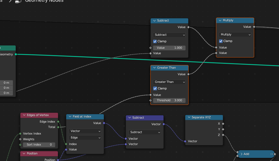
hard edge

This results in the wave being reflected from the edge :
reflected wave

Notice how the circular wave is reflected (upside down) behind the main wavefront.

$\endgroup$
4
  • $\begingroup$ Merry Christmas Mr. Sedman! (Nostalgia :D This was one of my first animations.. on a BBC Micro, in about 1983)... I wasn't contemplating a spring-simulation for this... but since you have. I wonder what a reasonable model would be, for reflections from fixed obstacles/edges...? $\endgroup$
    – Robin Betts
    Commented Dec 18, 2022 at 11:05
  • $\begingroup$ Merry Cristmas, indeed, Mr Betts :-) Good times with the BBC - I have similar memories :-) Very good point about reflections. My gut feel is that it should “just work” if some vertices are fixed. I’m going to have to give it a try now :-D $\endgroup$ Commented Dec 18, 2022 at 11:43
  • $\begingroup$ At first glance, I knew this is your work before seeing your name in print. You are one of people who inspire me to study maths & physics. :) $\endgroup$ Commented Jan 24, 2023 at 12:17
  • $\begingroup$ Sorry for the late acceptance. I didn't see the last edit. Very good work! $\endgroup$
    – TheJeran
    Commented Jan 30, 2023 at 15:29
2
+50
$\begingroup$

You can use one of the techniques described here:

How to create a simulation in Geometry Nodes?

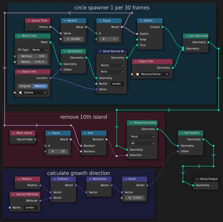
Considering at the time of writing this post the simulation nodes are at early alpha, I decided to use a Python solution instead (the oldest answer under the link) with the following geonodes simulation setup:

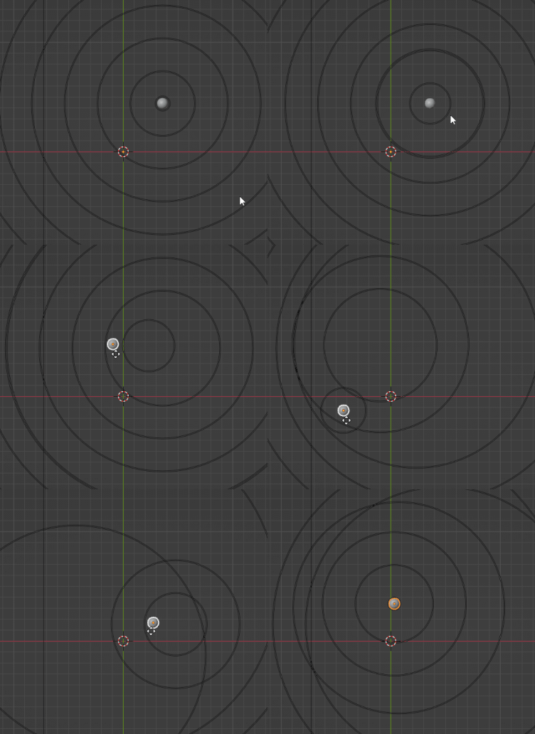
Perhaps it would make more sense to store a propagation direction rather than center… Anyway, now you can move the Sphere object spawning the circles, and they will still remember the original center:

Drawing the rest of the owl will depend on how you want the waves to overlap… For an interference you could spawn 10 (because I spawn up to 10 circles here) grids, and shrinkwrap (in geonodes using raycasting) them on Z axis onto the beveled circles, then summing the Z coordinates of the planes.

tested on 3.4β

$\endgroup$
4
  • $\begingroup$ Closer. Is it possible to only spawn waves when the propagating object has moved? $\endgroup$
    – TheJeran
    Commented Dec 3, 2022 at 20:18
  • $\begingroup$ @TheJeran sure, just store an attribute similar to center, but this time store it on each evaluation, and then you can compare it with the same index in the Previous Frame. In order to not spam circles you can read if the newest circle (index 0) is at least x away from its center… $\endgroup$ Commented Dec 3, 2022 at 21:18
  • $\begingroup$ +1 wow -> that's simulation before simulation in GN ;) $\endgroup$
    – Chris
    Commented Dec 5, 2022 at 9:54
  • 2
    $\begingroup$ +1 Love the owl reference. '..The completion of this derivation is left as an exercise for the reader'... $\endgroup$
    – Robin Betts
    Commented Dec 5, 2022 at 11:38
1
$\begingroup$

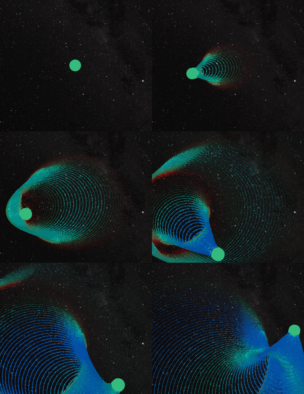
I was inspired by Markus' idea to propagate circles. This is with simulation nodes.

First:

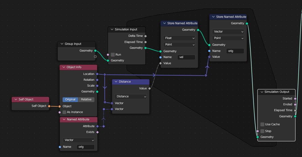
Create your propagating object and assign a velocity value 'vel'. This is simply the distance from the current location and the previous frames position.

enter image description here

Second:

  • Create a new geometry nodes object.
  • Sample the propagating objects location and the velocity. If the velocity is not zero spawn a new circle at that location.
  • Assign each circle a decay factor that increases with each frame. If that decay factor reaches a value, delete that circle.
  • Combine the velocity and decay factor to scale circles curve radius.
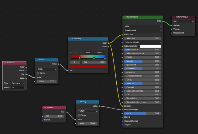
  • Send the velocity to shader attribute to color the waves

enter image description here

enter image description here

enter image description here

$\endgroup$

You must log in to answer this question.

Not the answer you're looking for? Browse other questions tagged .