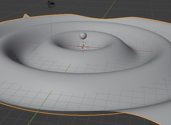
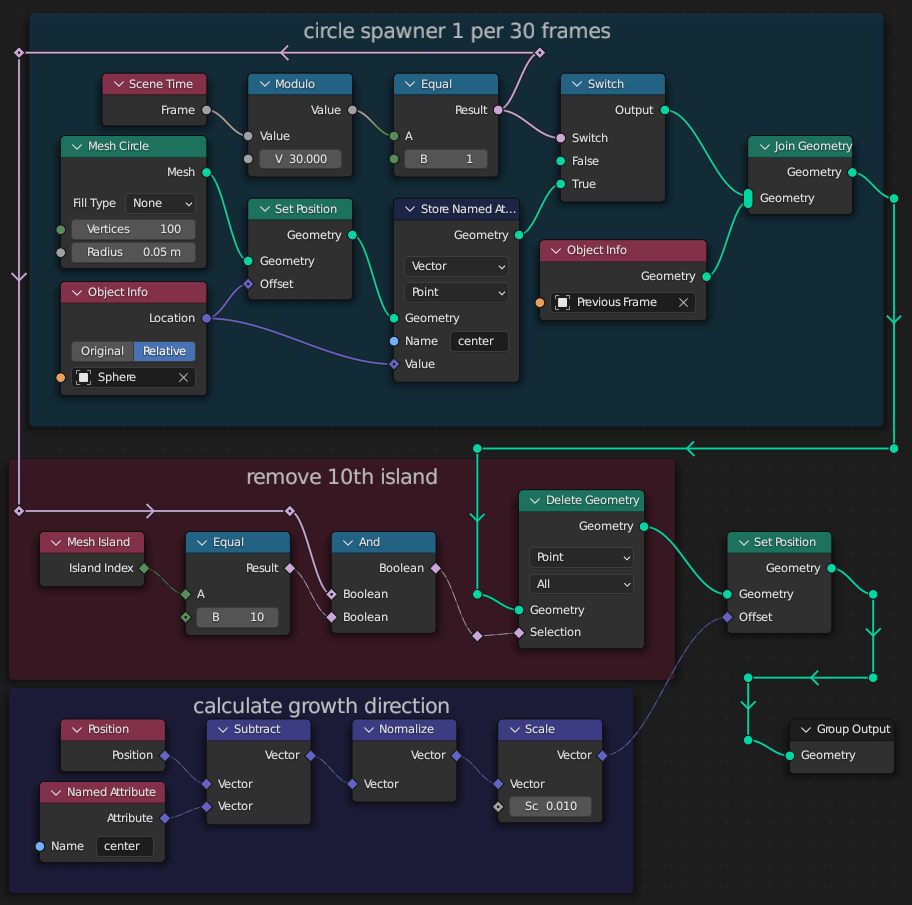
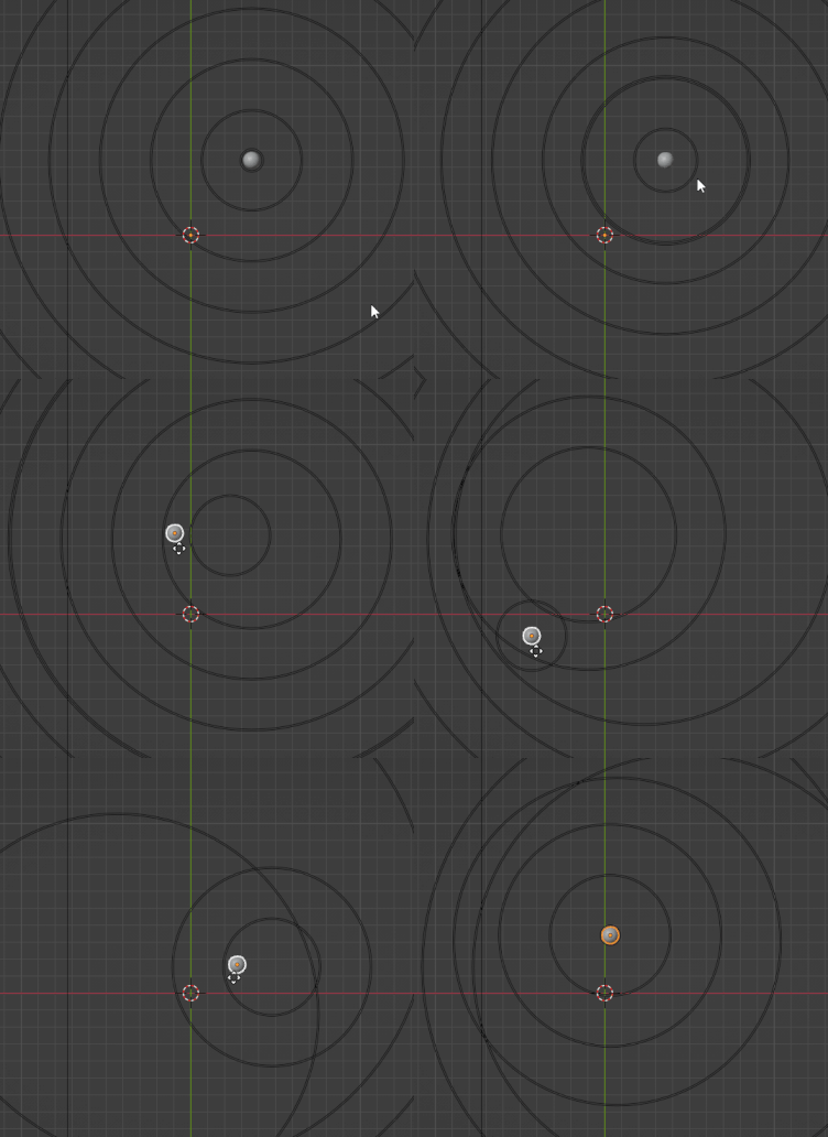
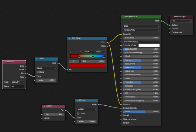
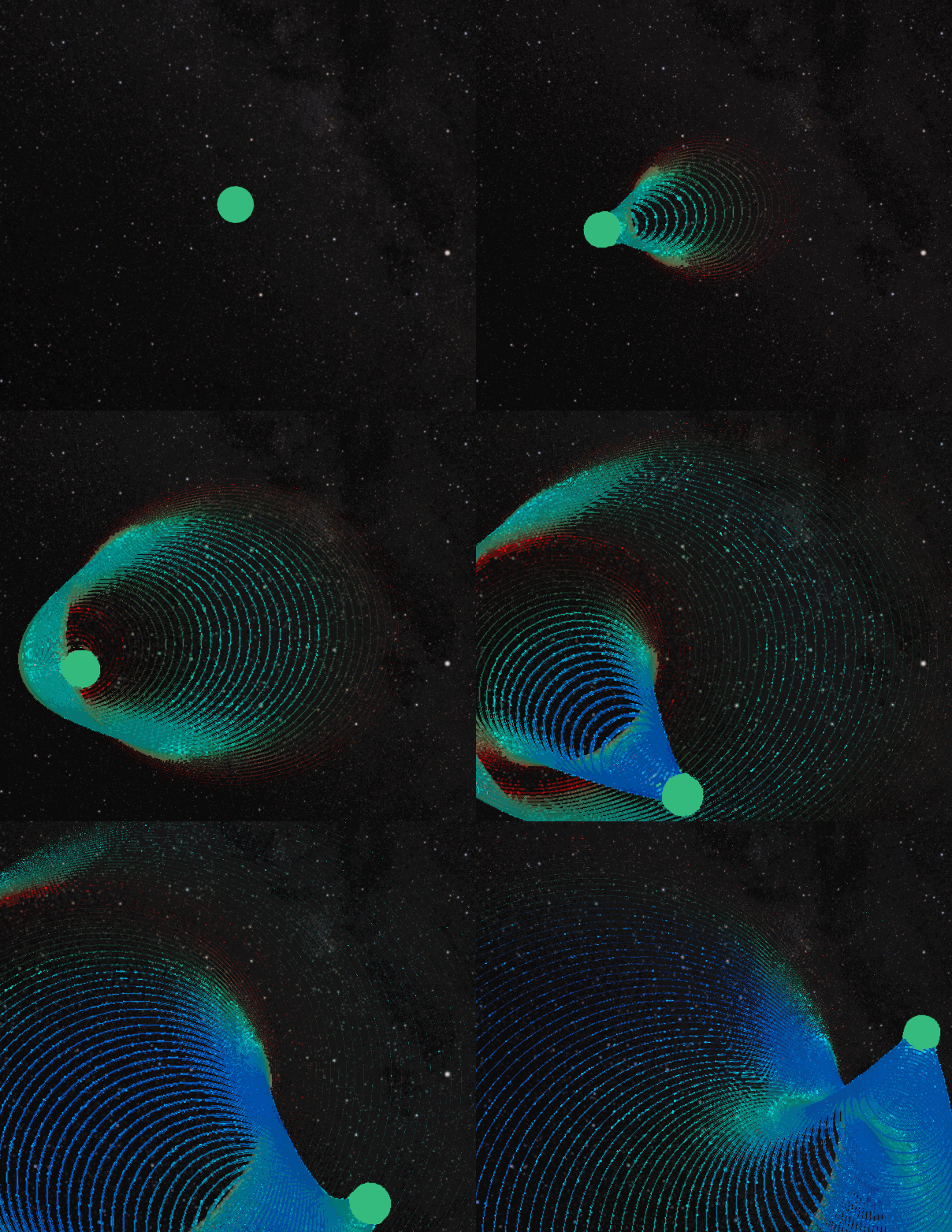
Yes - this is now possible with the new Simulation functionality being developed in Geometry Nodes :
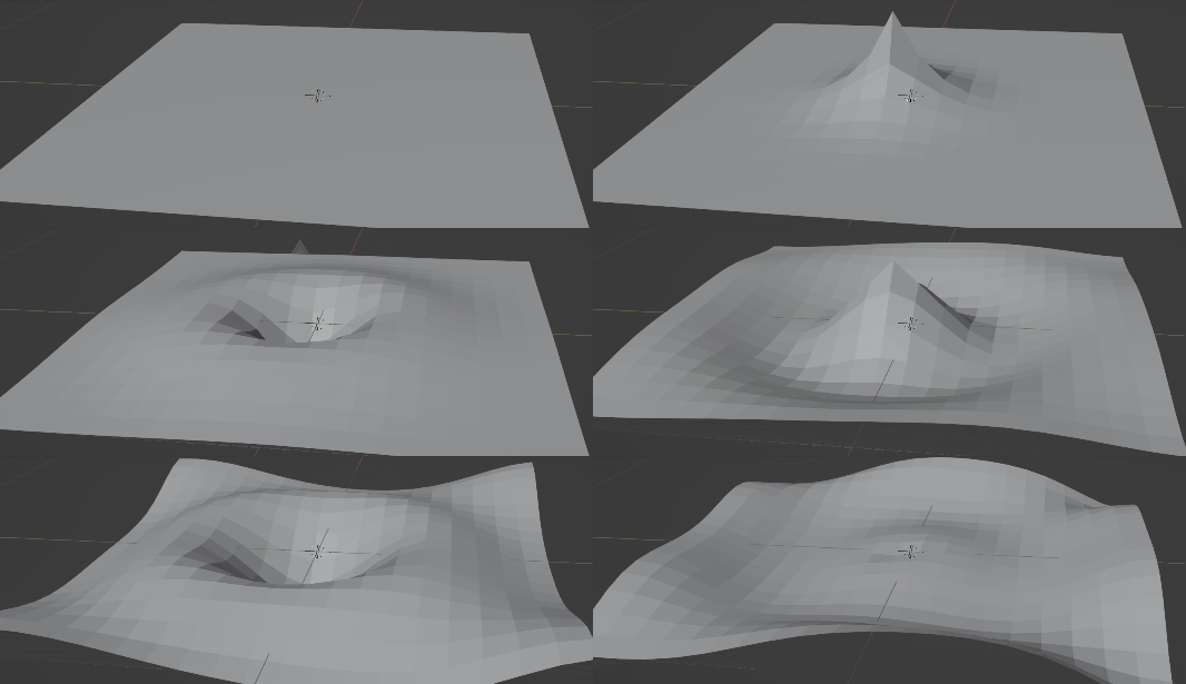
This can be achieved with the new 'Simulation' functionality of Geometry Nodes - where the state from a previous frame can be used to build the current frame using nodes. Note that the functionality is only currently available in the latest Alpha daily build in an "experimental" branch of Blender (https://builder.blender.org/download/experimental/ - see "Blender 3.5.0 - geometry-nodes-simulation") and is subject to change and/or may not make it into the standard build of Blender.
The Simulation Nodes extension provided additional "Simulation Input" and "Simulation Output" nodes - anything within the two nodes will be used to calculate the changes when changing animation frame.
So, in order to animate a mesh in this way we need a number of things :
- We need to be able to displace part of the mesh - either by proximity to another mesh/object or mathematically (eg, as a Sine wave)
- Each point in the mesh needs to have a Velocity and effective mass (we'll assume the same mass for every point and so don't need to store it). This allows it to continue moving and have an energy that can propogate through the mesh.
- Each point needs to be affected by the displacement of its neighbors.
- Each point will be locked in position except for its Z position (so it can only move up and down)
- We need to calculate the new position and velocity each frame.
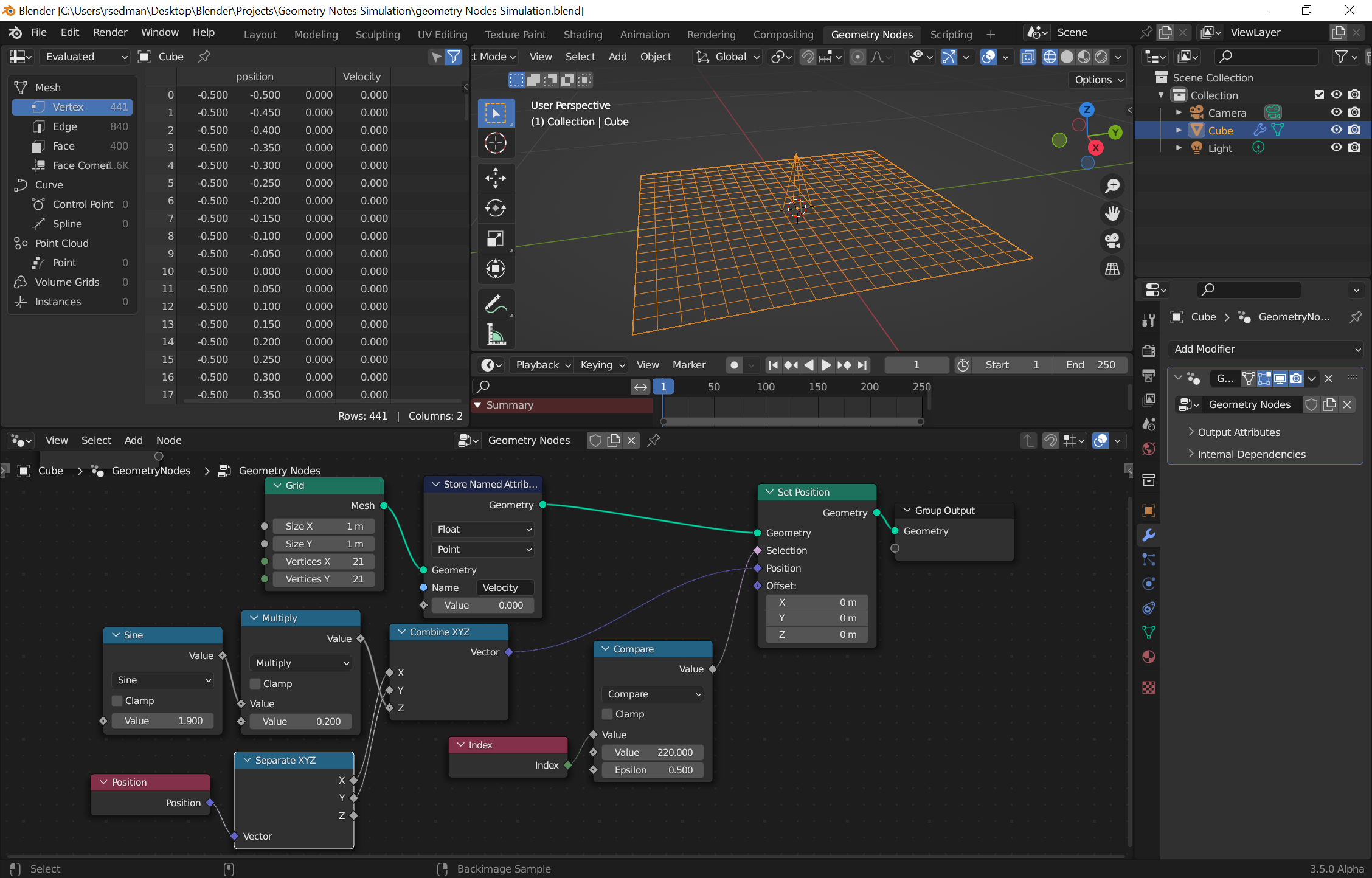
We need to store the velocity for each point in the mesh and we can do this with a Named Attribute.

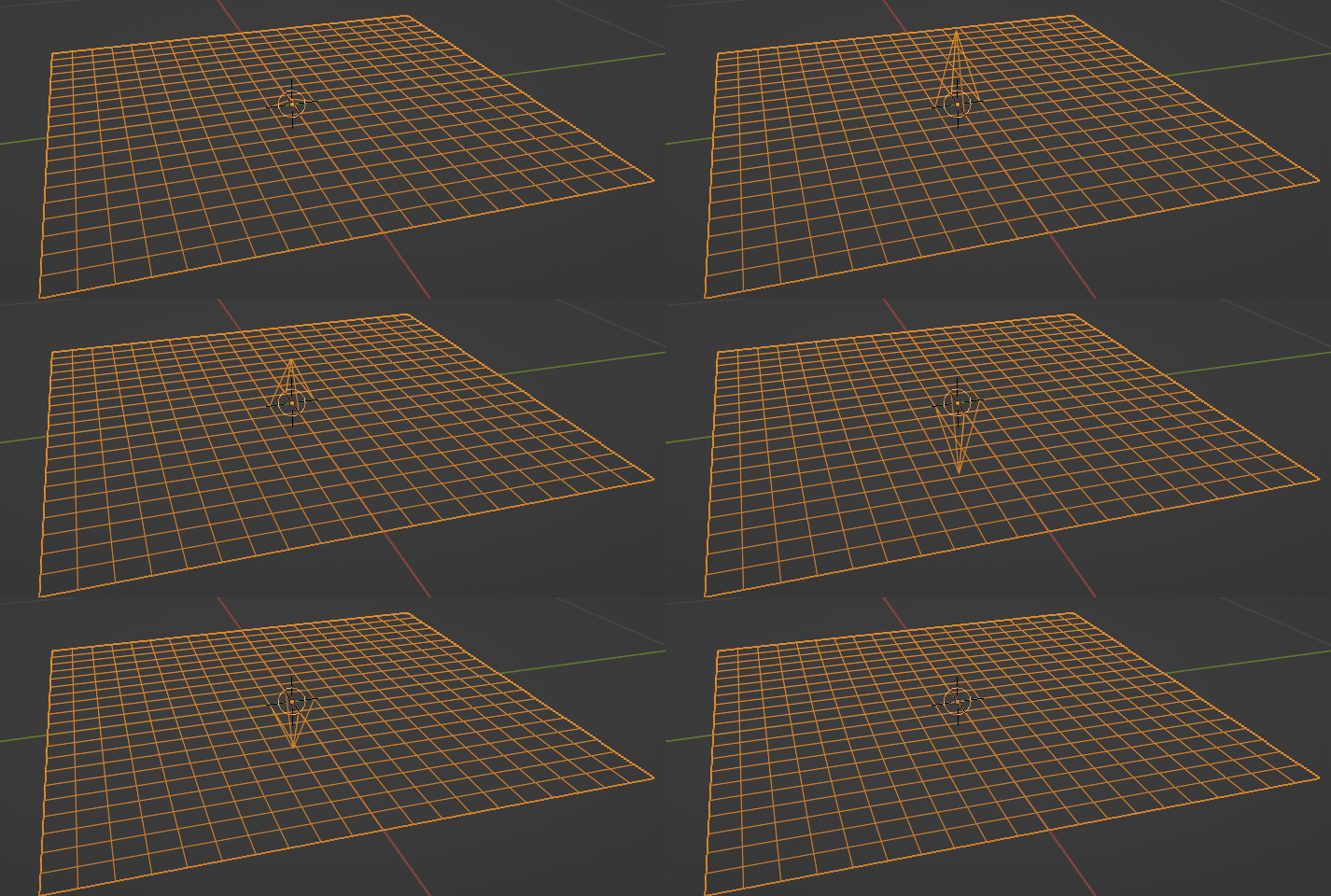
We can then add the displacement. I've opted to do this mathematically, but it should be possible to base this on proximity to another mesh (just more complicated). I used a Set Position node to set the Z coordinate based on a Sine wave that can be animated. Note that I've set which point to animate by calculating the index based on the known dimensions of the Grid (in my case 21x21 grid so the centre point (row 11, column 11) is "21*(11-1) + (11-1)" = 220).
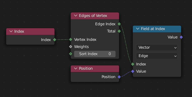
Calculating the displacement from its neighbors is a bit more tricky since we need to know which vertices it's connected to and their position. This isn't easy to do, but one way is via the Edges of Vertex node. This retrieves the Edges that are connected to the vertex with an index that can be used to select each edge.
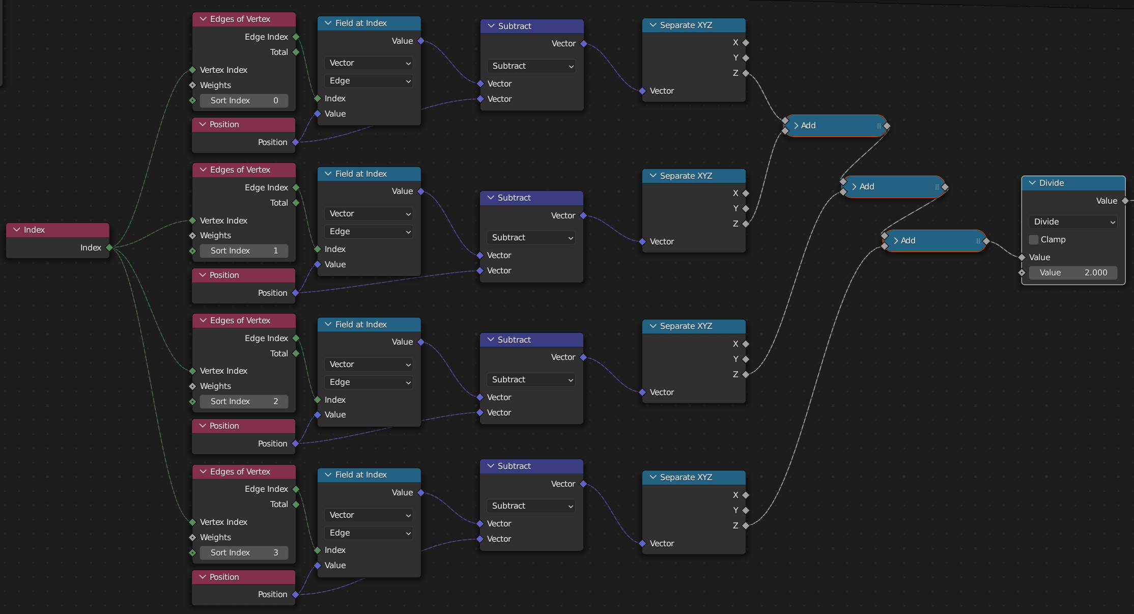
Unfortunately there isn't a simple way to retrieve the actual vertex position of the neighbor but we can retrieve the Position of the edge which will be half-way between the current Vertex position and the neighbor's position.
Summing the (up to) 4 vertices and dividing by 2 will give us the average displacement (since there are 4 vertices and the displacement is only half as far due to being the midpoint of the edge). Note that the Sort Index is incremented to select the edge being sampled.
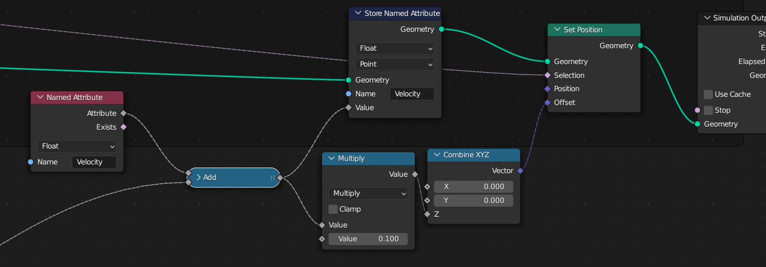
The output of the above can now be used to adjust the stored Velocity of each verted - by retrieving the current velocity, adding in the new 'pull' of the surrounding vertices, and then storing the Velocity again. In addition, the new velocity can be used as a Z-offset to the current Position of the vertex.
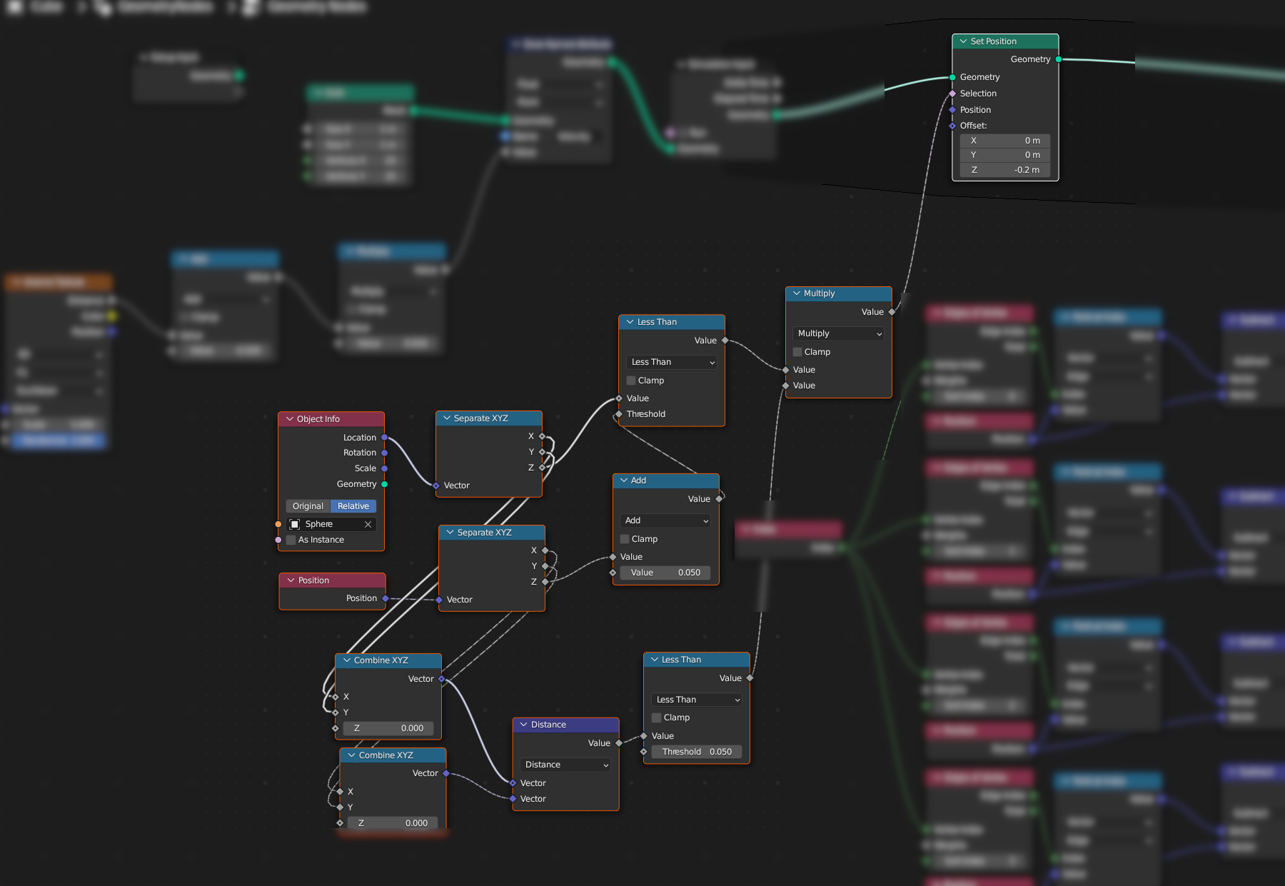
The new Simulation Input/Output nodes are used to surround the nodes that need to be evaluated on each frame - so the displacement of a vertex and the calculation and application of the velocity. This gives something like the following node structure :

You can add some damping to the motion by adding a Multiply node before storing the new Velocity - eg, to multiply by 0.99 to damp the velocity by 1% each step. This will calm the motion over time. Here's the final result with increased grid resolution :
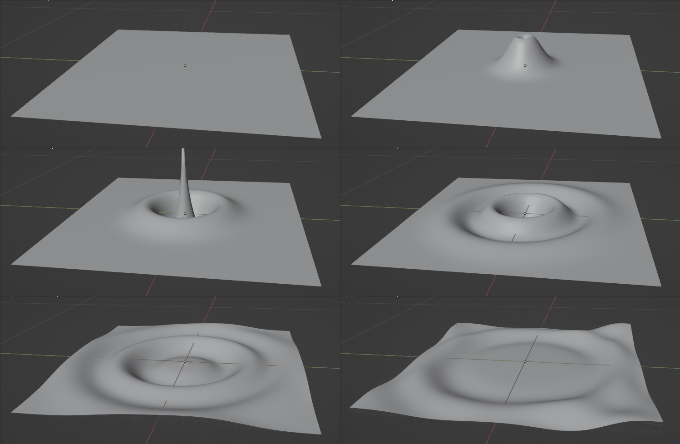
Blend file included (but requires Blender 3.5.0 Alpha (or later) Geometry Nodes Simulation build 
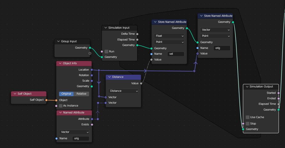
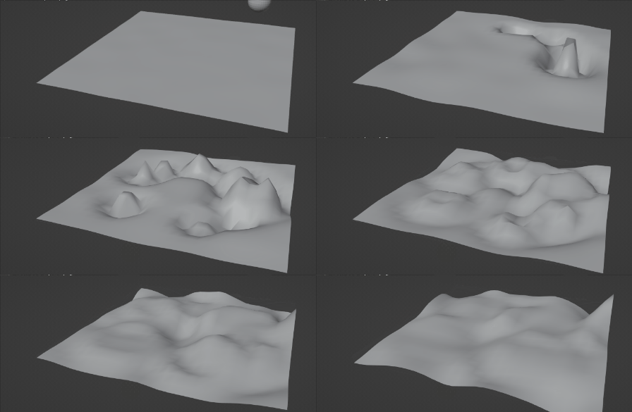
EDIT : Just to prove that it's possible to affect this based on mesh proximity, here's a bit of a dirty hack to the nodes to use the position of another mesh (animated to collide with the surface) to affect the velocity of the grid :
EDIT: From Robin Betts suggestion as to reflections, it's relatively easy to add a 'hard edge' to the grid where the vertexes are fixed - and this results in reflections from the boundary. This can be achieved by using the Total output of the Edges of Vertices node - as this will be 4 for any vertex in the bulk of the grid and less than 4 for any edge or corner vertex (which will be missing one or more neighbours) - see the selected nodes in the following image :
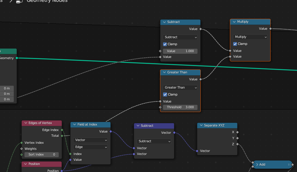
This results in the wave being reflected from the edge :
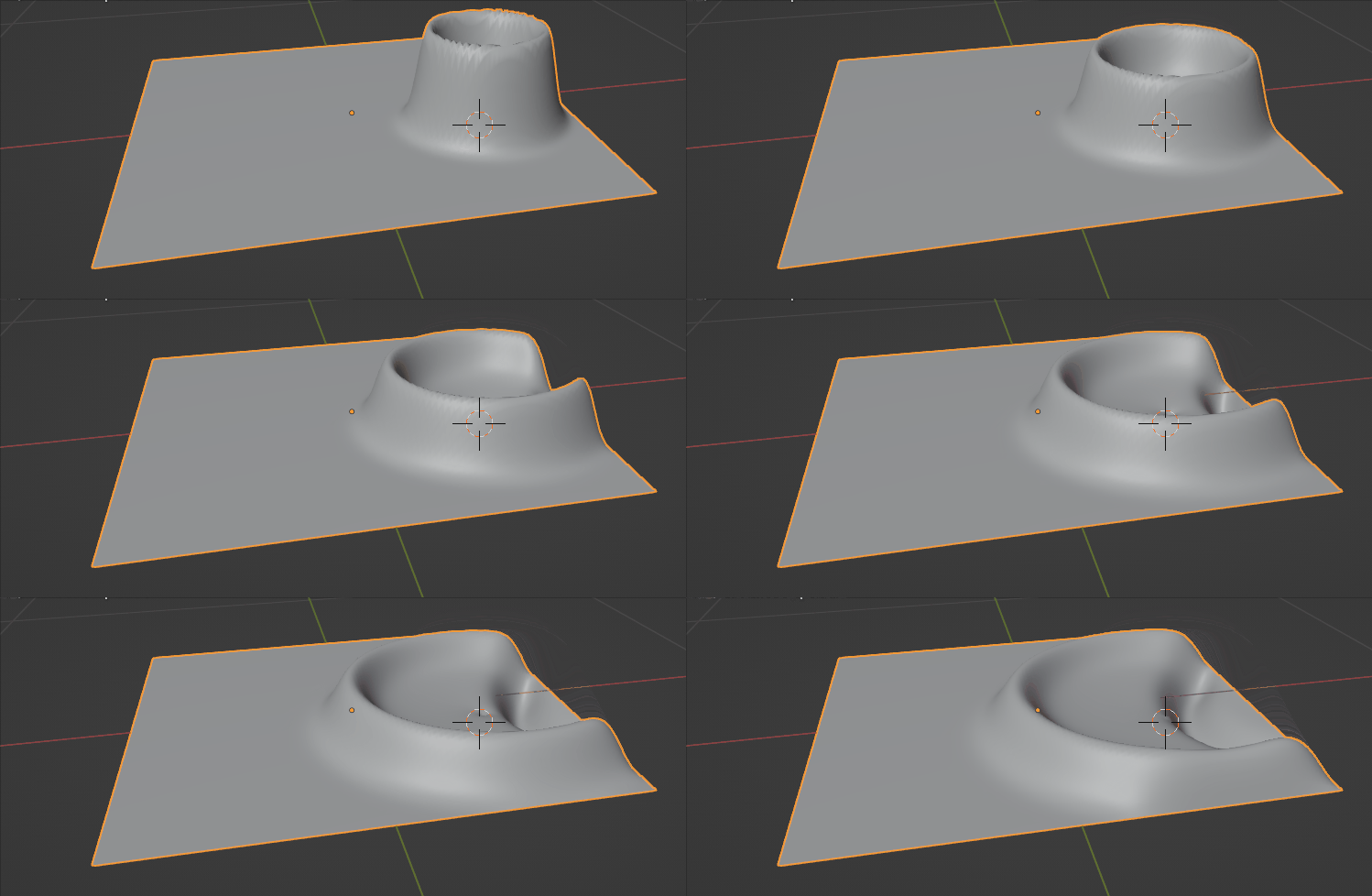
Notice how the circular wave is reflected (upside down) behind the main wavefront.

