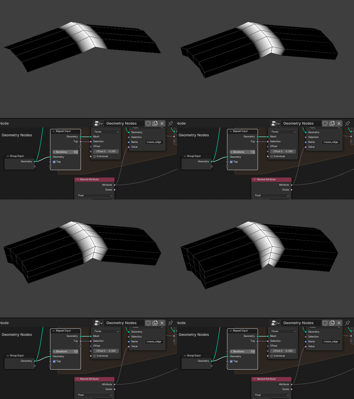
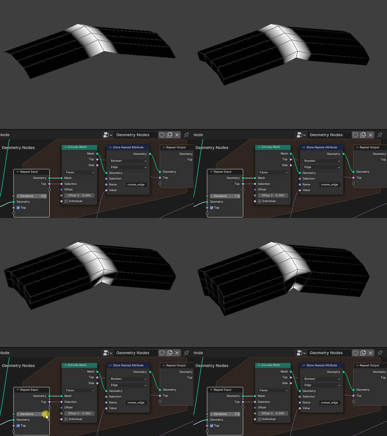
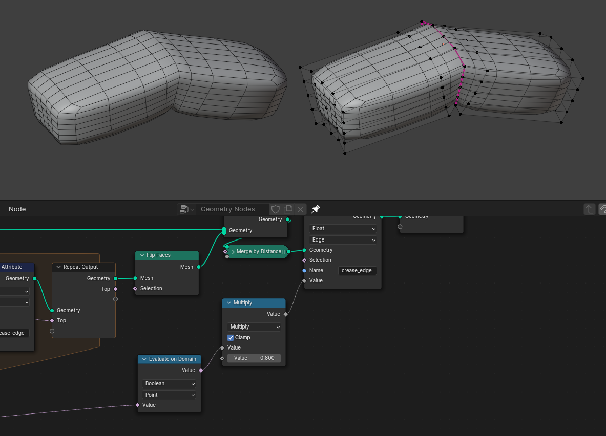
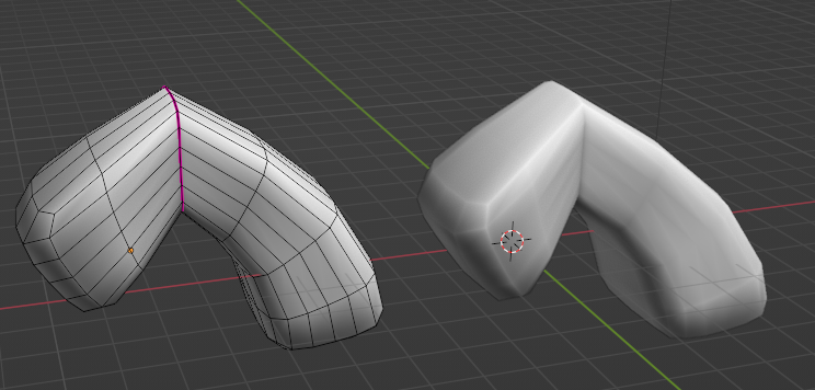
is there a way I can extend the edge crease to the adjacent edge when using the extrude node in geometry nodes? This is what I curently have (left), this is what I get when I apply the modifier (center) and this is what I'd like to have (right)
-
1$\begingroup$ I don't know if maybe there's a Blender 4 easy way to do it, but in the past... Geometry Nodes: set sharp or crease attribute for an edge $\endgroup$– Markus von BroadyCommented Dec 12, 2023 at 11:43
-
$\begingroup$ @MarkusvonBroady I'll try to look more into it, but rn I still can't do it right $\endgroup$– AlexCommented Dec 14, 2023 at 0:13
3 Answers
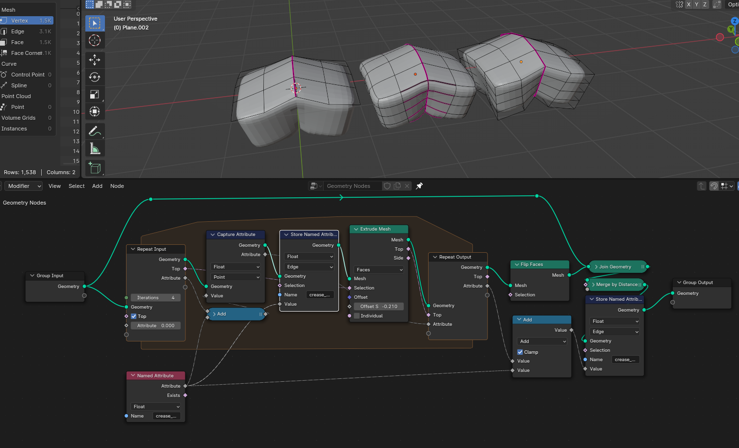
The trick is writing sharp attribute into vertices, then read back from vertices to edges:
This requires using topology nodes. Edges of vertex so that we know that the vertex is connected to a sharp edge. And Edge vertices, both of vertices is from sharp edge.
-
$\begingroup$ Thank you, works very well. However I noticed the node setup works better if the last math node is switched to minimum rather than multiply that causes flickering in some cases. Also, why is the subtract node needed before the edge of vertex node? $\endgroup$– AlexCommented Dec 16, 2023 at 9:03
-
$\begingroup$ Yes, if you look at image I've made an update and replace multiply by minimum. Subtract is used to reverse the order (maximum value goes first). $\endgroup$– CrantiszCommented Dec 16, 2023 at 10:28
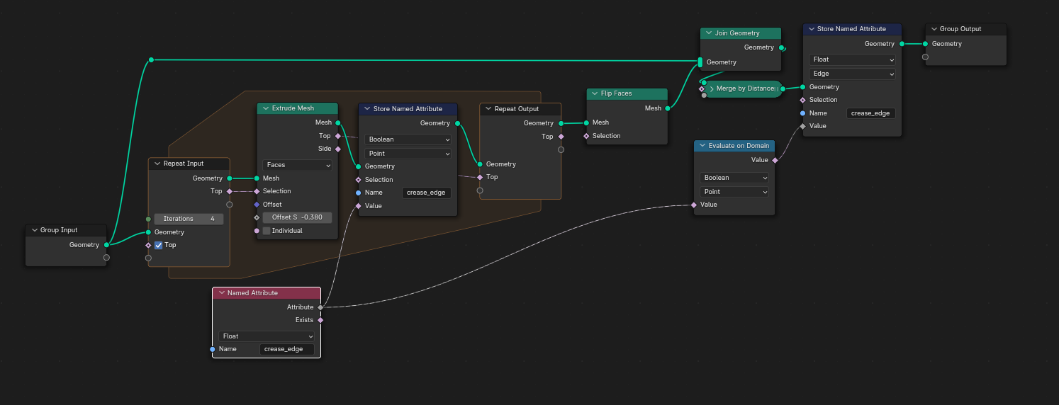
The Geometry Node modifier for this problem can be simplified to:
Instead of storing the crease_edge attribute in its native Edge domain we temporarily store it in the Vertex domain as a Boolean type.
Thus with every extrusion the extruded copy of the vertices will inherit their Boolean values from the previous iteration.
If the crease_edge attribute was stored in the Edge domain the newly generated Edges that are not copies of the previous mesh will not inherit any value, thus forming a gap in the edge loop.
(note that the highlighted edge in the first iteration is not selected, it is just difficult to visualize the Boolean Edge selection with the Viewer Node, so the display in the animated images is set to Point)
After the Repeat Zone the crease_edge attribute is stored back in the Edge domain as a Float type. To make sure the interpolation to Float values is done without including "half selected edges" we pass the attribute though Evaluate on Domain node set to type Boolean in Point domain. This will select only edges which have both of their vertices selected.
Optionally - after the Evaluate on Domain node you can include a Multiply node to change the value of the edge crease if needed.
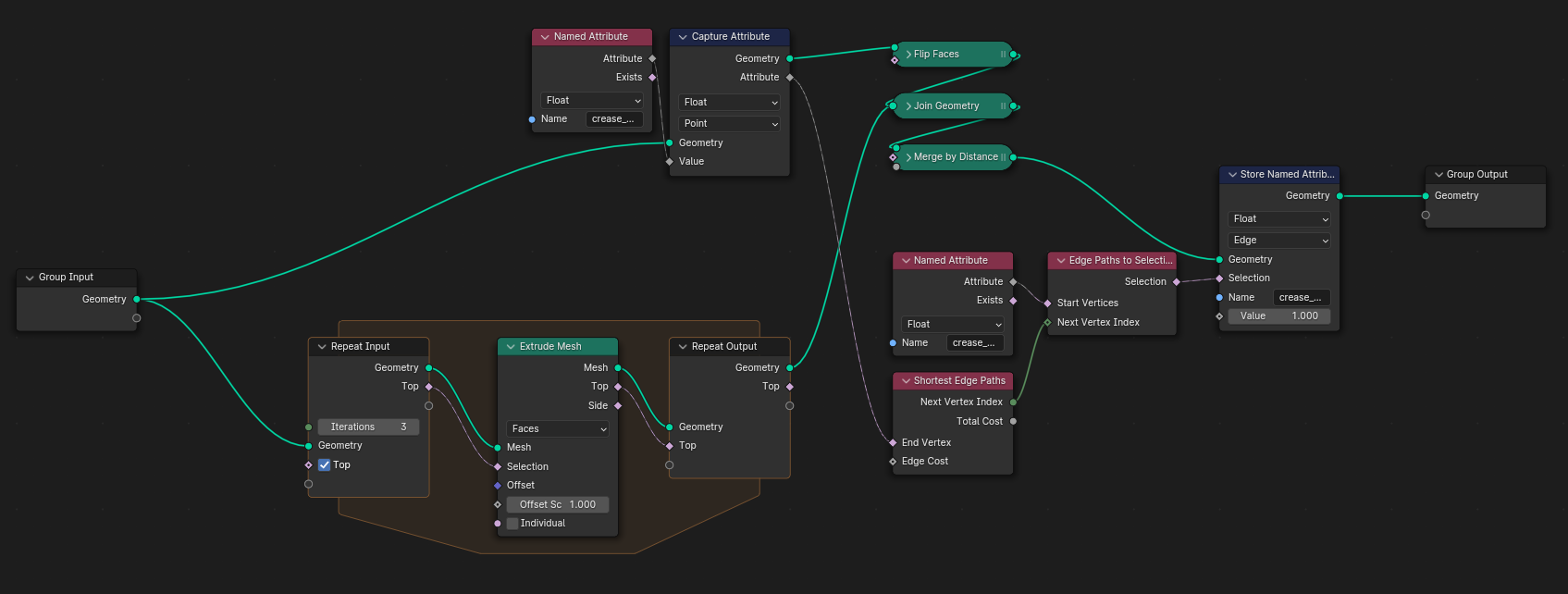
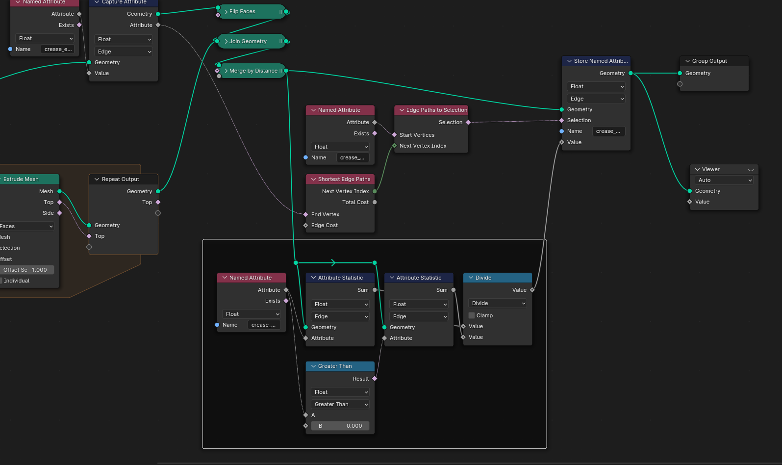
Another possibility: use of shortest edge paths after the loop.
Capture edge crease attribute of the original edges (either on edge or point domains).
Use it as end points selection for the shortest edge paths node.
Use the crease as start point on the resulting mesh.
Set the crease_edge attribute to the value for the edges selected by shortest paths.
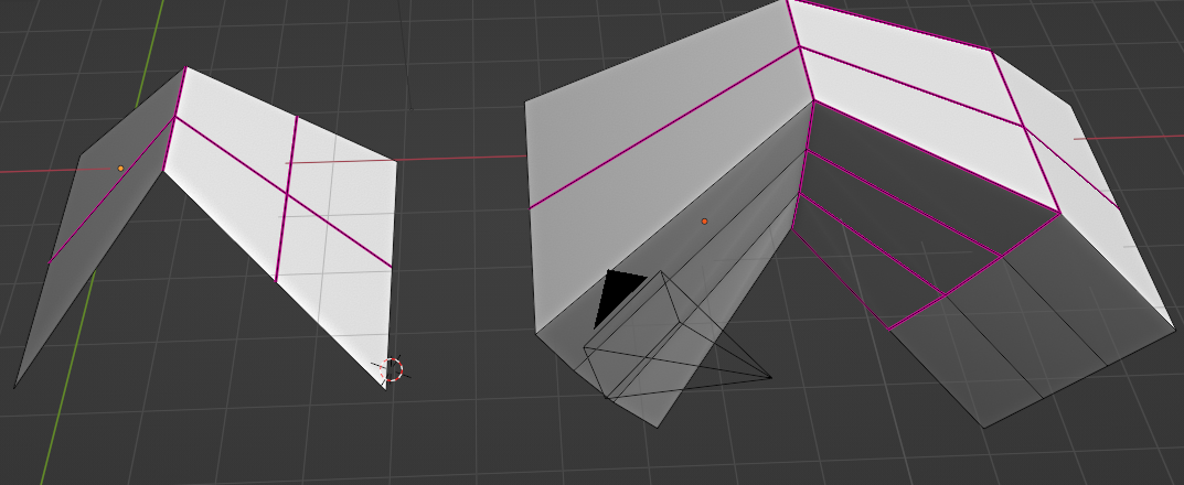
Note: the issue to go throught point domain, instead of edges, is that you'll propagate crease along other parts of the mesh if there is several creases in the base mesh/surface.
For instance:
And this is not the case using shortest paths because all is done in edge domain concerning the creases:
Other point: if you want to report the (mean) crease of the original surface (instead of a constant value), you can add these nodes:
-
$\begingroup$ That is very clever, I didn't think of using shortest edge path. I was able to get rid of the propagated creases by removing the side loops from the selection but this is a much simpler solution $\endgroup$– AlexCommented Dec 21, 2023 at 8:08
-
$\begingroup$ Strangely, this does not work if you invert "end" and "start" vertices. I don't really know why but I suppose this is because end vertices are to be in a separated (because captured) data. $\endgroup$– lemonCommented Dec 21, 2023 at 8:21

