2
$\begingroup$

I am a railway modeller, I can design and add basic textures in SketchUp, no problems.

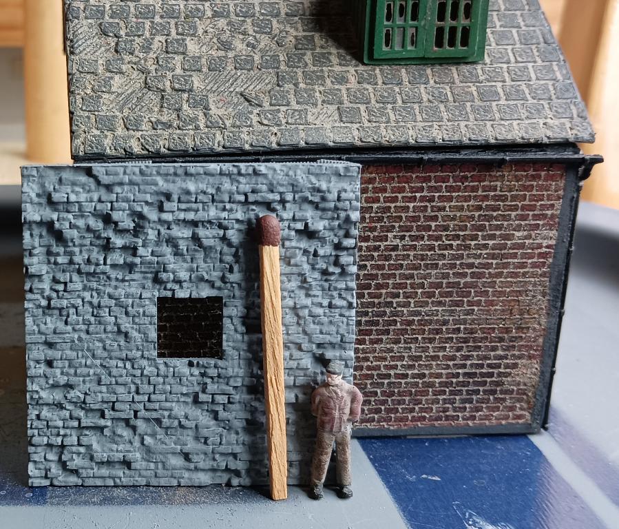
I needed to up the texture levels quellenform instructions put me right so now Walls with real life textures are possible. I made a couple of how too videos aimed at the newbie like myself on my YouTube Channel. I am trying to pass on the knowledge and the response was great.

Test piece

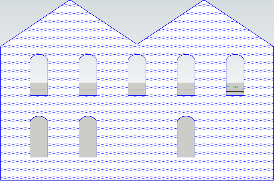
My question is: how do I convert a SVG/STL/DAE type file in Blender to a single mesh with no subdivisions so I can add a displacement texture. I can then cut out windows using the Boolean method later once the texture is applied. I have Construction lines addon installed, would this help?

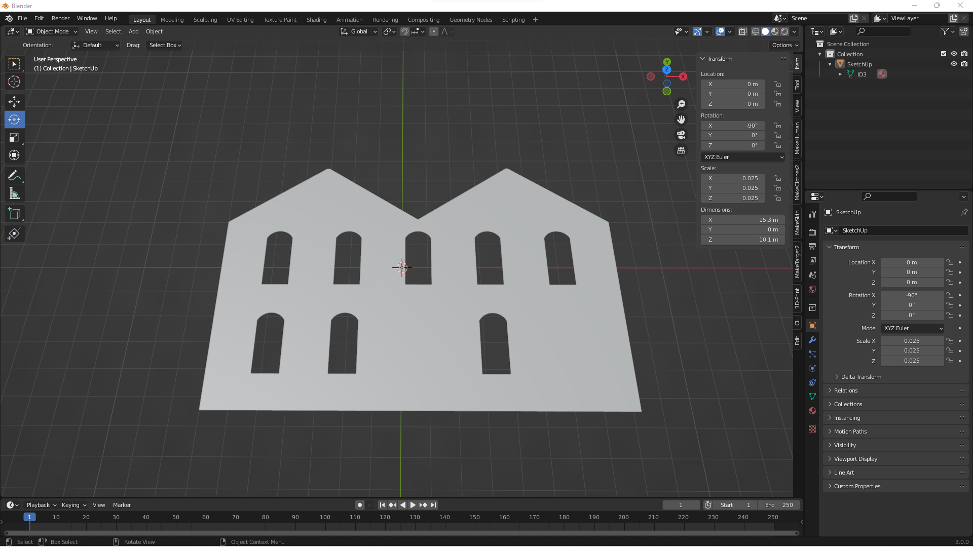
Type of drawing I want to convert

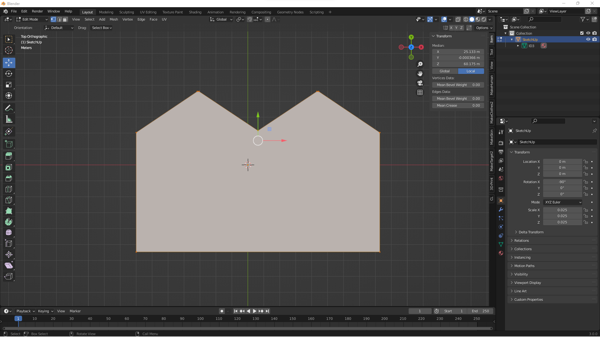
Import SVG, Limited dissolve works well. I try and subdivide and only the edge gets subdivided?

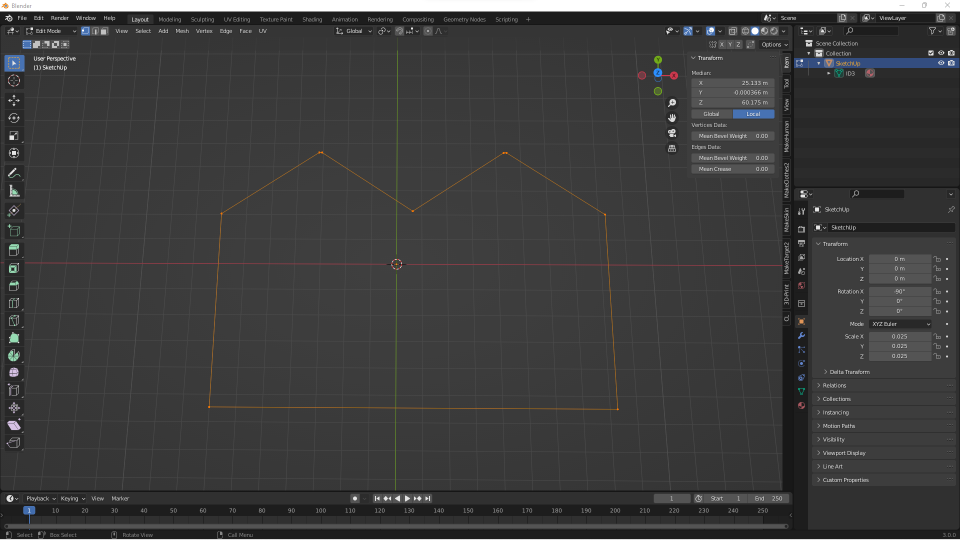
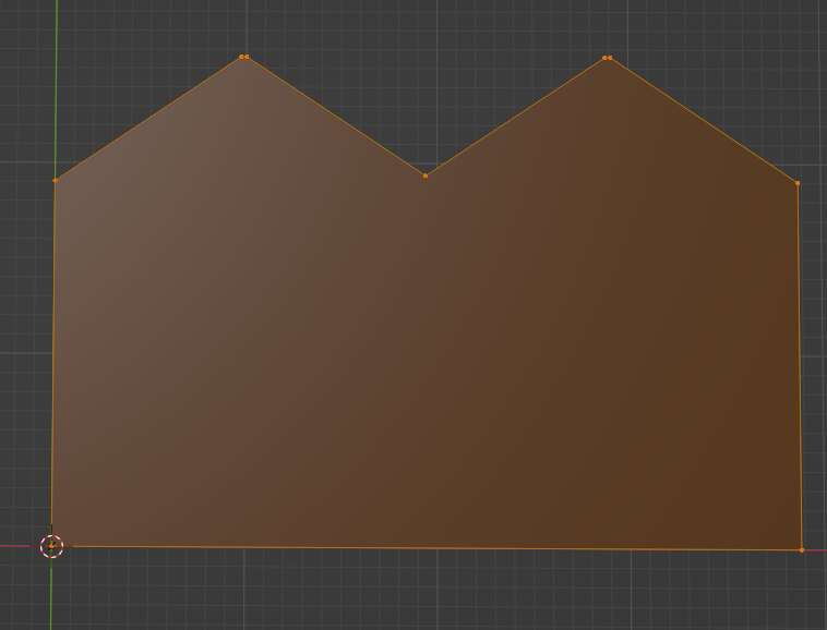
SVG imported

Limited dissolve

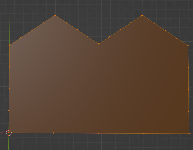
Subdivided only edges affected

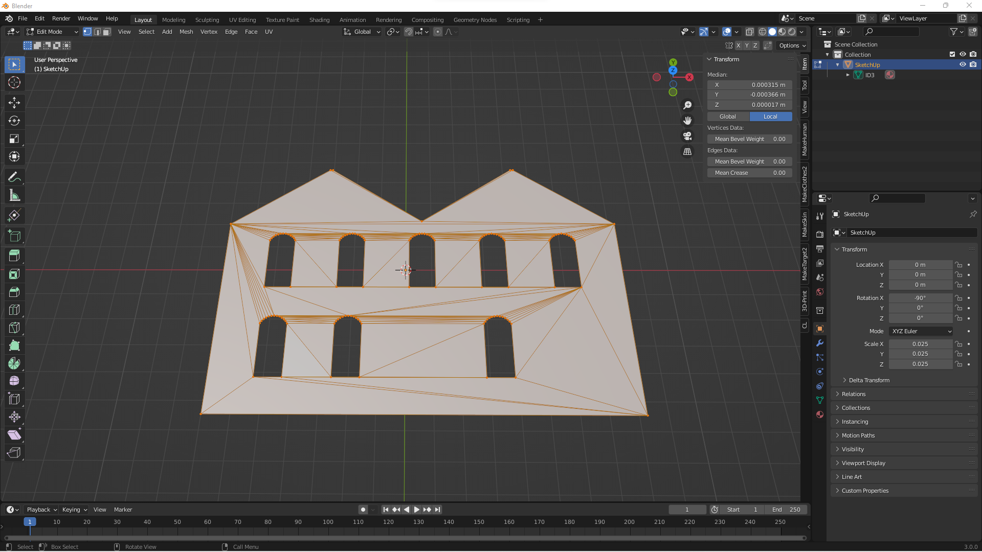
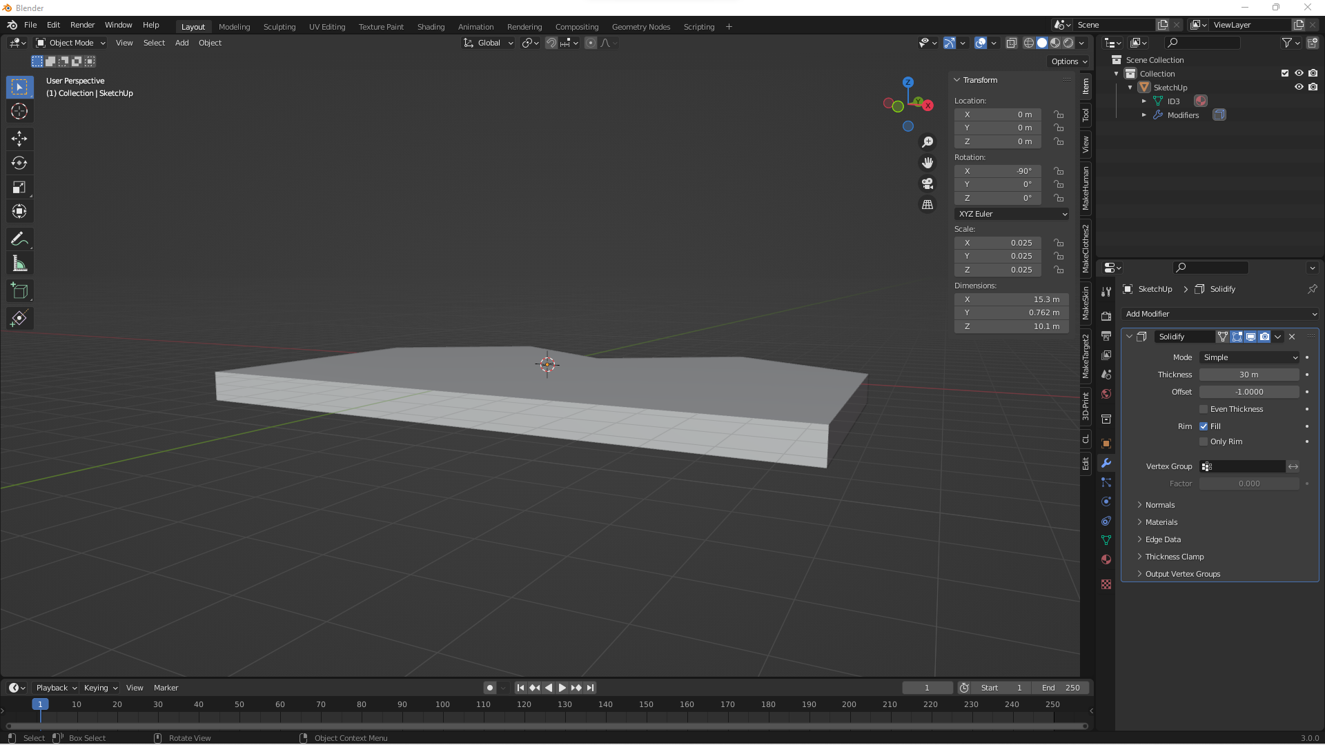
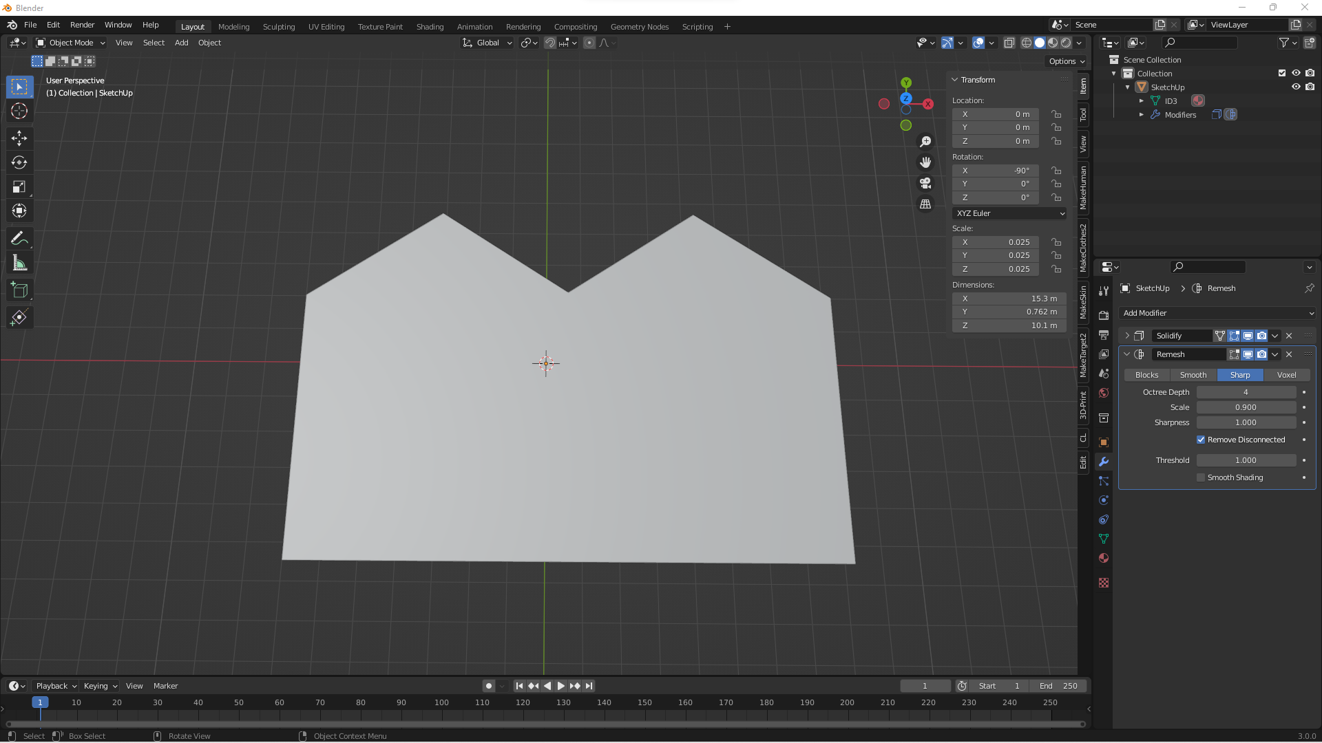
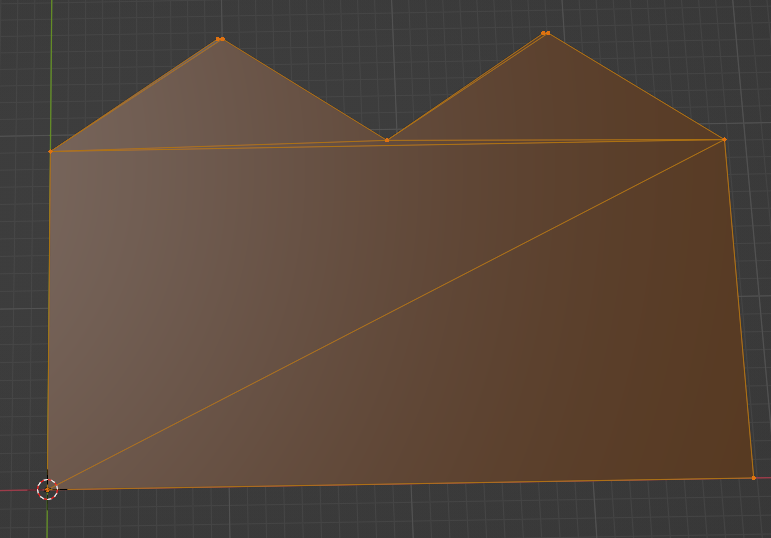
I seem to be doing something wrong as I get to the REMESH stage and when I apply it the CPU slows down and the object disappears. DAE file from SketchUp Original geometry Removed all internal geometry Edit mode add face F_KEY Solidify Remesh

I thank you very much for the time spent educating a numpty like me. I have been going through the node sequence box by box trying to work out what does what. I have come unstuck on the first hurdle. On the Map Texture Scaling Box the blue box Map Range node has no node connectors. How do I connect that box to the Bounding Box node and Position node? enter image description here
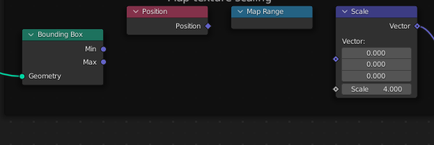
I have updated to the latest Blender and following your Node flowchart, I have MADE SOME CHANGES and the model is working. I need to get into the finer details on how everything works.

$\endgroup$
4
  • 1
    $\begingroup$ Hi :). To remove subdivisions on a flat surface, use the Limited Dissolve command or Decimate Modifier $\endgroup$ Commented May 11, 2022 at 12:30
  • 1
    $\begingroup$ Now on topic: If you have already successfully applied the Boolean Modifier technique to a section in the inner area, why not repeat the same technique with this outer shape? So extrude this mesh with Solidifier, then a grid which is also extruded with Solidifier, and a Boolean modifier which leaves the part of the intersection of these two parts with Intersect. It is certainly not the most performant solution, but it works and the mesh should be clean enough for further processing. $\endgroup$
    – quellenform
    Commented May 11, 2022 at 16:20
  • 1
    $\begingroup$ The unused inputs are hidden to save space, press CTRL+H to unhide $\endgroup$
    – quellenform
    Commented May 13, 2022 at 20:09
  • $\begingroup$ Success, I have found that adding a DAE file converted to a curve works well. Also to replace the original curve with a new one, some geometry links in the NODE EDITOR must be removed and reconnected after new curve added. $\endgroup$
    – Eddy
    Commented May 16, 2022 at 8:54

1 Answer 1

3
$\begingroup$

OK, I think now it's time for you to get to know Geometry Nodes ;-)

Of course you can do all this with modifiers and various edits directly on the mesh, but this is a desctructive edit, and I strongly assume you are talking about procedural creation of your mesh.

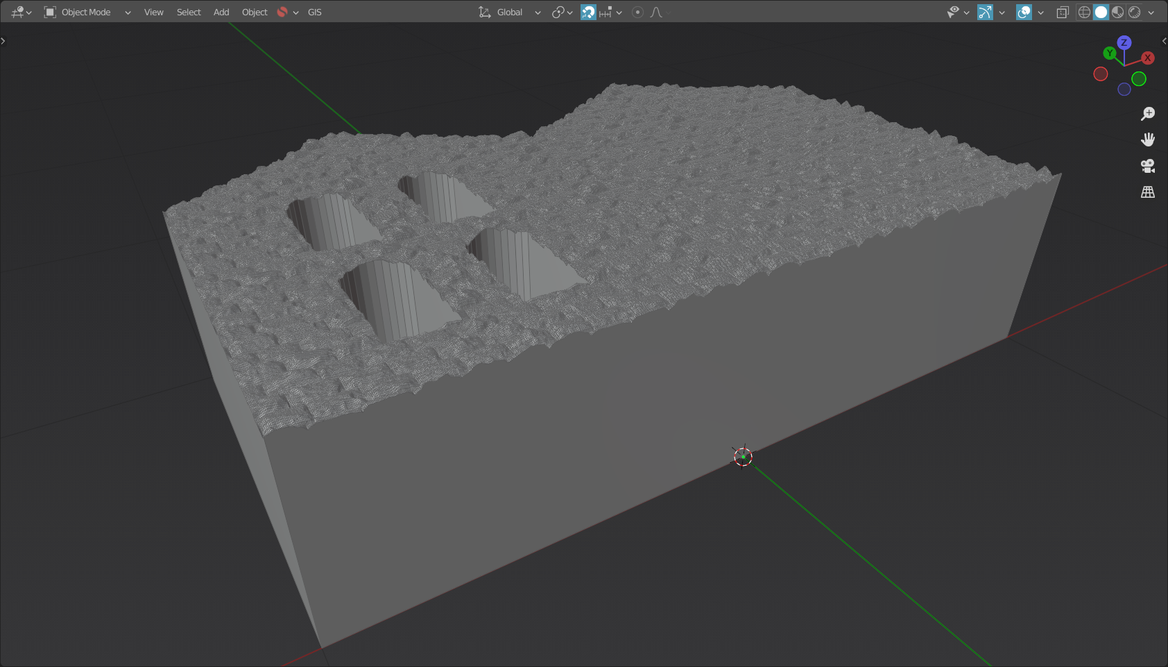
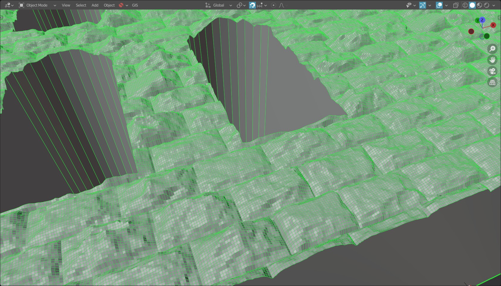
In this example, I created the entire object directly from a curve-based shape using Geometry Nodes:

Screenshot 1

As you can see, it's a relatively clean and high-resolution mesh that you can always make finer.

Screenshot 2

The nodes that created this result look like this:

Nodes

I explain briefly what I do here:

  1. First, I create a grid, and set the size and resolution here. The dimensions should be a bit higher than your shape. You influence the resolution with the number of vertices of the grid, and additionally with the node Subdivision.

  2. I capture the dimensions of this grid with the node Bounding Box and then map the positions of the individual points to an area that can then be used for texture mapping. The size of the texture is defined with the node Scale (Vector Math).

  3. Then I include the actual displacement map with the node Image Texture, which receives the previously calculated positions as vector input. The height of the displacement is controlled by the node Multiply (Math).

  4. In the next step I apply the displacement to the grid with the node Set Position. The node Transform defines the final position of the grid.

  5. At the same time I get the shape of the grid. In this case it must be a curve. In your case you have the optimal data when importing SVG, and if it is still a mesh, just transform it into curves beforehand. I fill this curve(s) with the node Fill Curve (with the settings N-gons) so that I have a clean mesh as a base. Furthermore I apply the node Extrude which gives me an extruded mesh like the modifier Solidify.

  6. Now comes the computationally intensive part: I combine these shapes with the node Mesh Boolean (with the setting Difference), so that I finally get the result where only the surface of the mesh is affected by the displacement, but still only the surface is replaced by a clean grid.

  7. In the final step I apply the original shape with flipped faces on the bottom side and merge the vertices with the node Merge Vertices.

With that, you should have your 100% procedural mesh.

Note:

  • Since everything here is procedural, a lot of processing power is needed. So always try changes on a less high resolution mesh first (reduce the subdivision)! Increase the subdivision only at the end, as soon as you are satisfied with your result.
  • The shape to which you apply the displacement must always be a little larger than the shape you want to edit.
$\endgroup$

You must log in to answer this question.

Not the answer you're looking for? Browse other questions tagged .