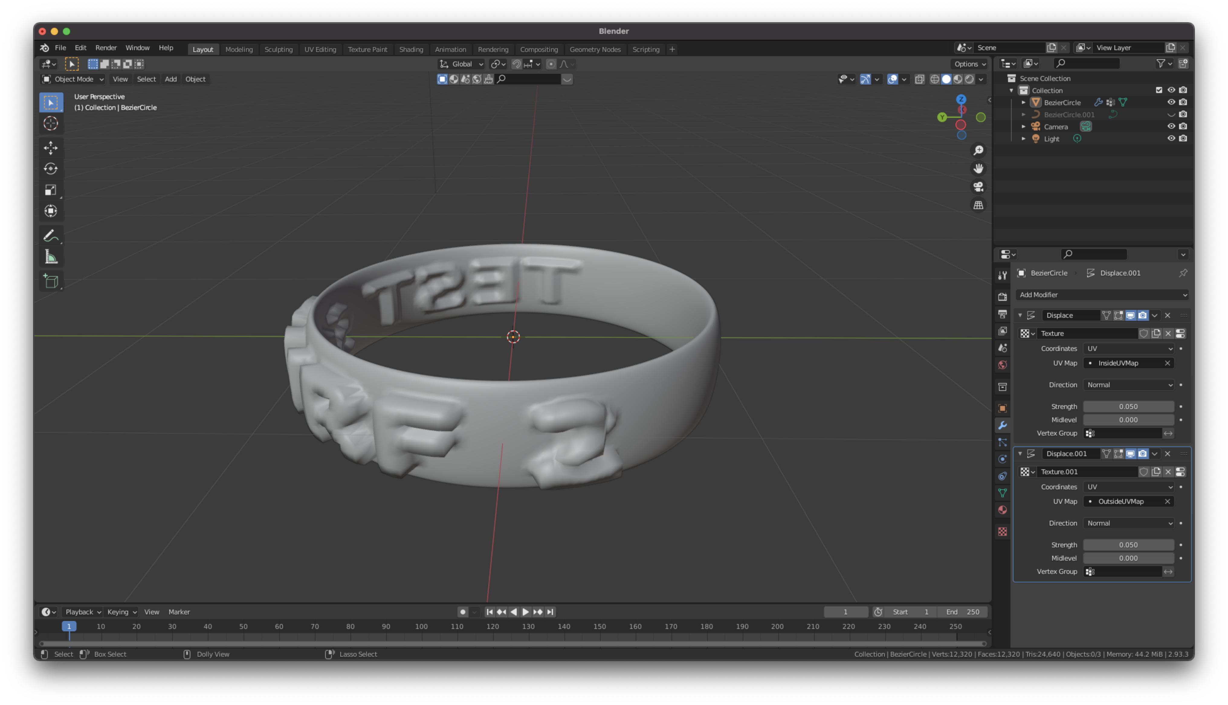
My attempt to accomplish this was to create 2 separate UV maps that only map the vertices in the region I want to apply the displacement maps to. Then I apply 2 different displacement modifiers and use one UV map for each. This did not work as expected. Here is what I did specifically:
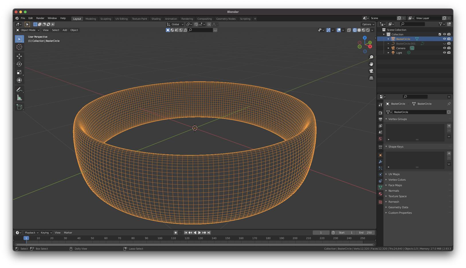
- Create a mesh. In my example I am using a simple ring model made by using a smaller oval curve as the bevel object for a larger circle curve. After increasing the Resolution Preview I then convert this object to a mesh.
Delete existing UV map
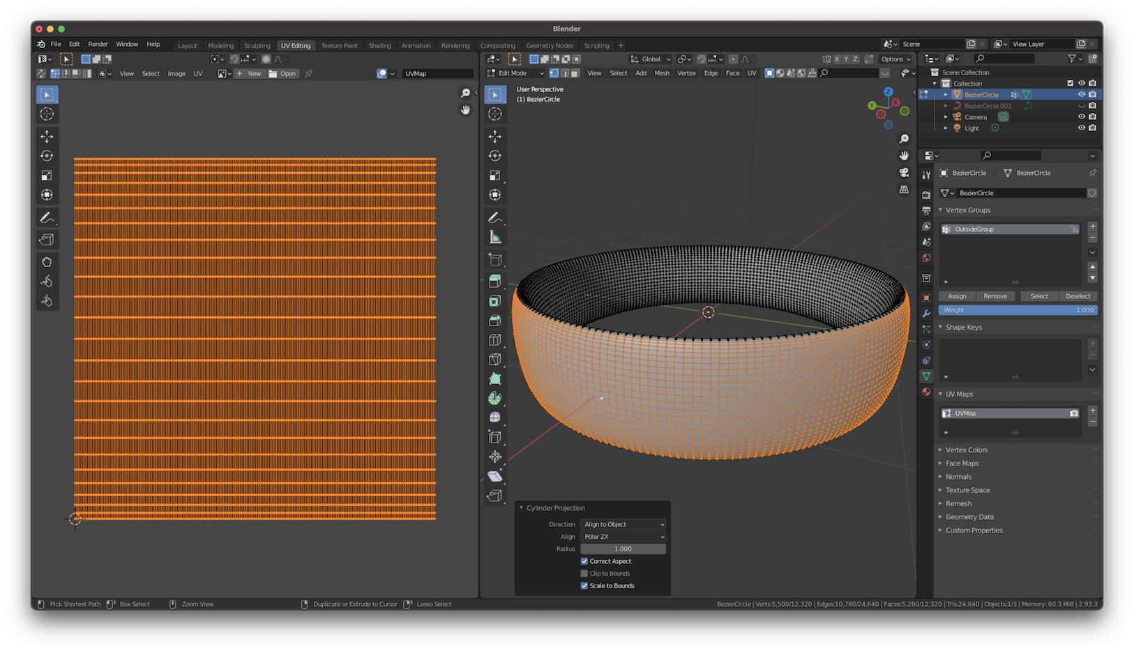
Select first subset of vertices for one of the displacement map. Generate new UV map with
UV > Cylinder Projection. Direction should be align to object and select Scale to Bounds
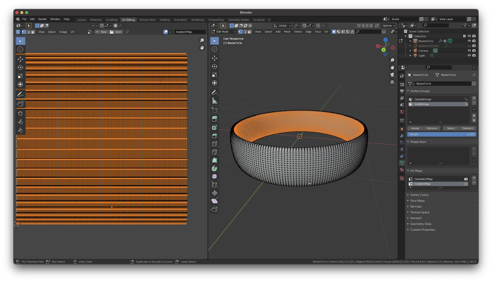
- Select the next subset of vertices. Create a new UV map (Object data properties > UV Maps > Plus button), and then generate the new map with a Cylinder Projection again
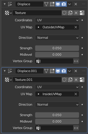
- Create 2 displacement modifiers with the coordinates set to UV and the 2 different UV maps selected. These are the displacement maps I've used and the resulting mesh
This almost works as I expect. Each displacement map is in the area I want it to be, but the outer surface has both displacement maps applied. I noticed when I created the second map, the original map's vertices seemed to be under the new map. However I am not able to delete these. I am assuming this is the root of the problem, but I don't know how to solve it.
Please let me know if I need to supply additional information

