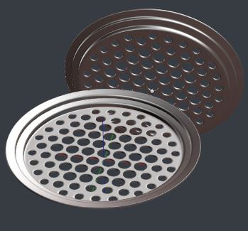
I'm a beginner so maybe this is really simple, but I'm trying to make multiple holes through a cylinder from top to bottom. As a beginner, I tried boolean, but that of course breaks the mesh into pieces.
I'm sure there's a way how to do it. Thank you very much for answering.
-
2$\begingroup$ This is a tricky thing to do, especially as a beginner. If it doesnt have to be done with geometry I would use a material with transparency controlled by a texture with holes. If it needs to be a geometry I would use boxes instead of cylinders with cut out front/back walls, then I would connect them using edit mode and F hotkey, when done I would use subdivision surface to smooth it out. It is not trival, I will answer it more fully when out of work, unless someone else answers by then :) $\endgroup$– internetofmineCommented Jul 11, 2018 at 8:03
-
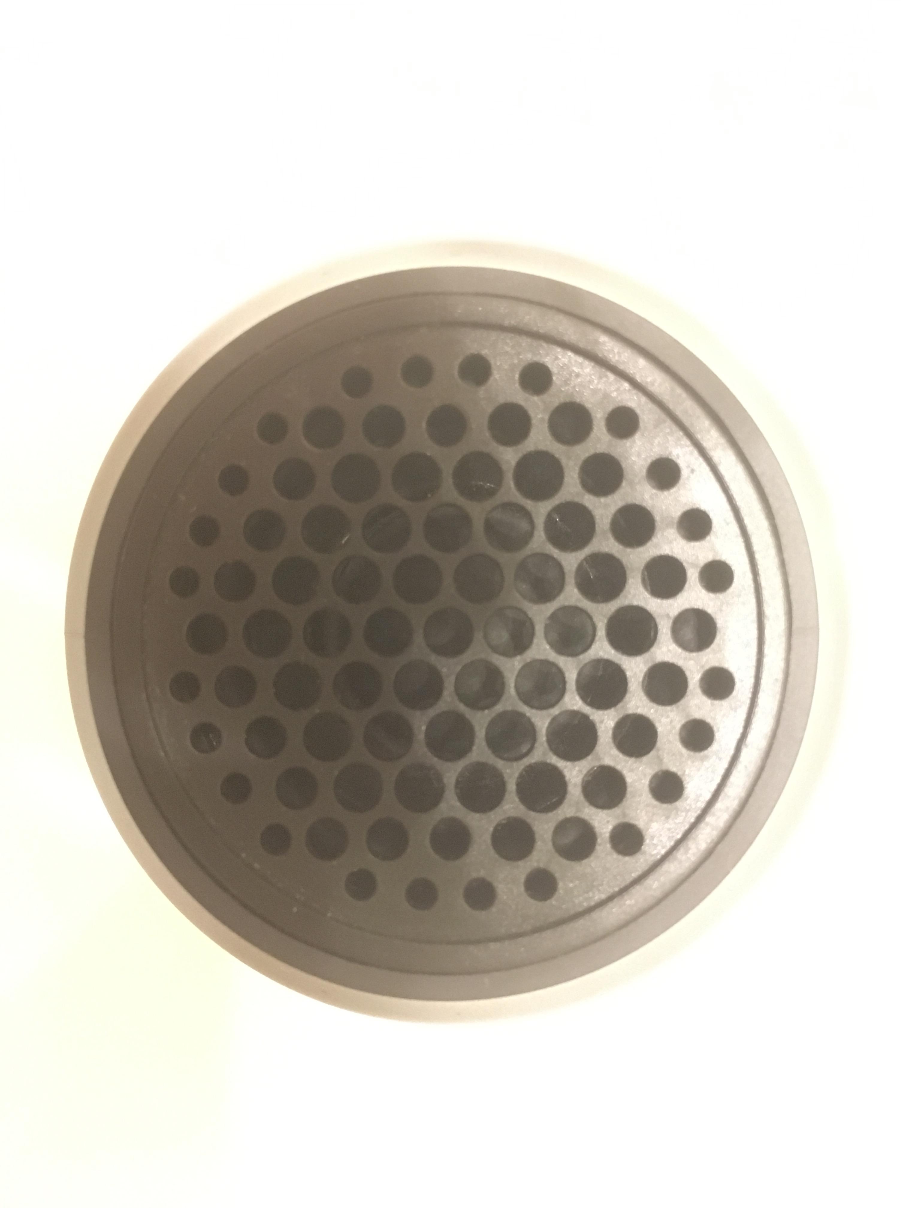
$\begingroup$ I would use this photo as a background and create as many circles (like 12 vertices circles) and join the holes between them with F, you will have triangles but it's ok, then select all peripheral vertices, extrude them and W > Looptools > Circle: zupimages.net/up/18/28/o54d.jpg $\endgroup$– moonbootsCommented Jul 11, 2018 at 8:21
-
$\begingroup$ What did you mean by "Breaks the mesh into pieces"? I just created a Cylinder and an array of Cylinders and then used the Boolean Modifier to create the Difference. I can then apply the modifier and get rid of all the extra objects. $\endgroup$– robCommented Jul 12, 2018 at 10:08
-
$\begingroup$ rob: Well, can you then use subsurf? I tried this approach even with starting with high poly meshes, trying avoid subsurf, but still wasn't good and the mesh was not clear at all. As this is like 20% of the product I'm trying to model, it needs to be pretty detailed. Can you please show how does your mesh look? $\endgroup$– user3573289Commented Jul 12, 2018 at 13:57
2 Answers
Alright as promised, I am attaching images that should help to visualize what I am describing. It probably is not the only way of doing it, but it gives you fairly nice control, no triangles and subdivides nicely.
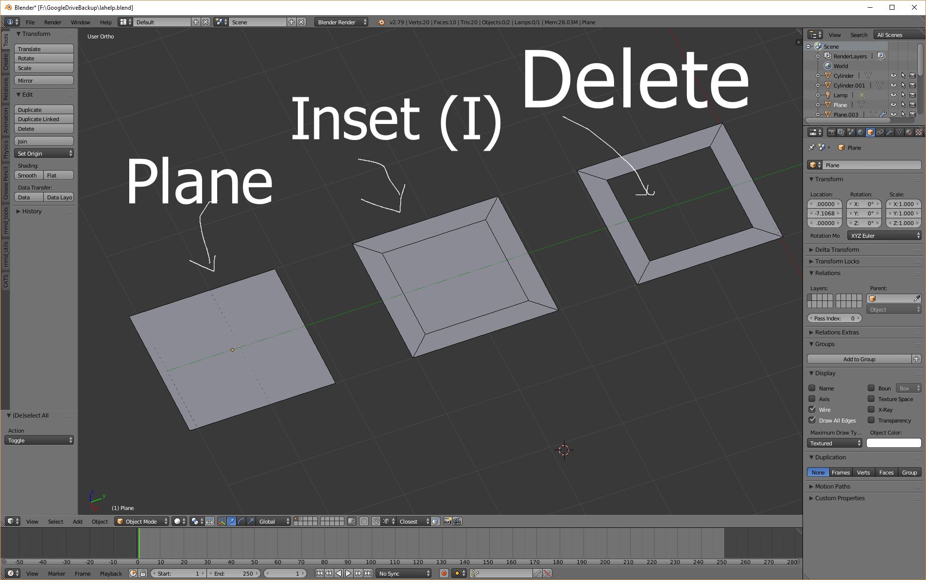
First I would create a plane, inset it using I and remove the insides with X.
Secondly I would arrange the shape of holes using the square-holes. I did less than you need, but I am lazy and I think it describes technique well.
Third thing would connecting all the holes using F, using extrusion, and removing doubles every now and then you should be able to get to get the fairly round shaped thingie with holes arranged as you want.
Next, I have extruded border out and smoothed it out pressing Space followed by 1 (this "spheres it out" as much as possible).
At this point I made sure to count how many vertices there are on the border of the object. For me it was 28.
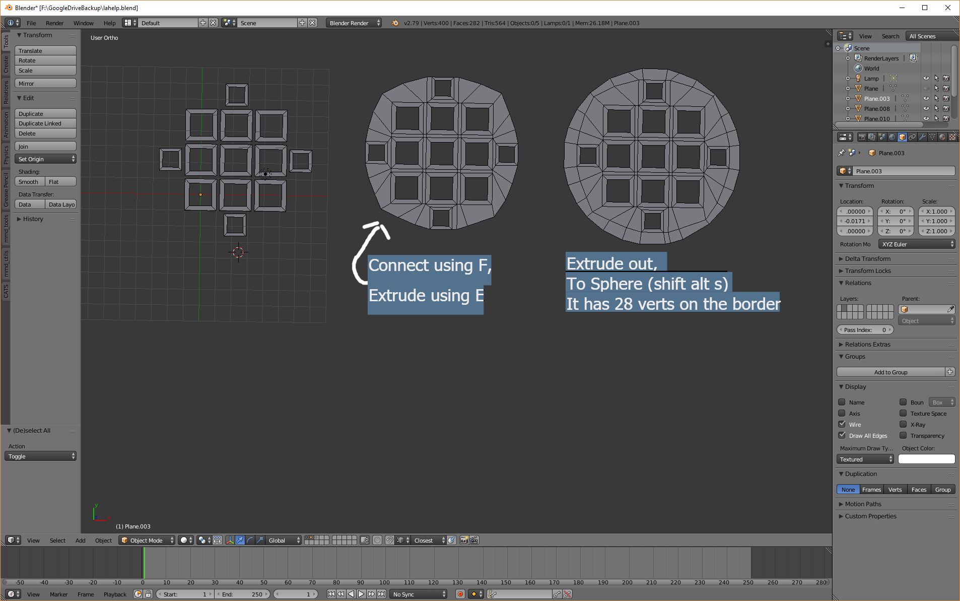
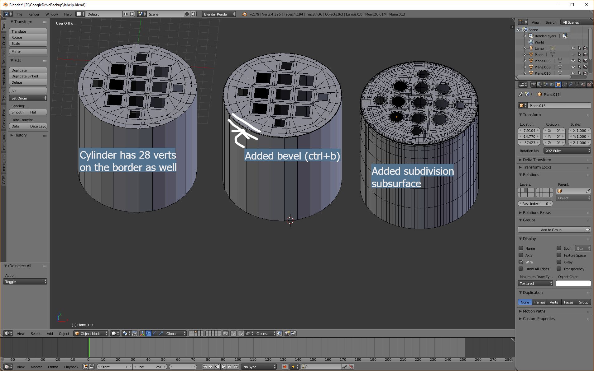
Then I have added a cylinder with the same amount of verts (28) and removed it's cap and then connected it with the hole-thingie, Using F.
Then I have selected the edge and beveled it a bit using ctrl+b.
Finally added subidivision surface modifier and smooth shading.. and you're done :)
I think this information helps you out, if not, let me know, I will try to describe it more clearly :)
-
$\begingroup$ Lot of work, but looks really promising. I will try probably after the weekend and I'll definitely mark your answer as correct. Thank You! $\endgroup$ Commented Jul 12, 2018 at 13:58
-
$\begingroup$ Yar it's always a lot of tedious work required when you want your stuff look good in 3d :) You could try @Robin Belts answer as well, it does require more steps but is also a very promising way of achieving your goal :) $\endgroup$ Commented Jul 12, 2018 at 19:05
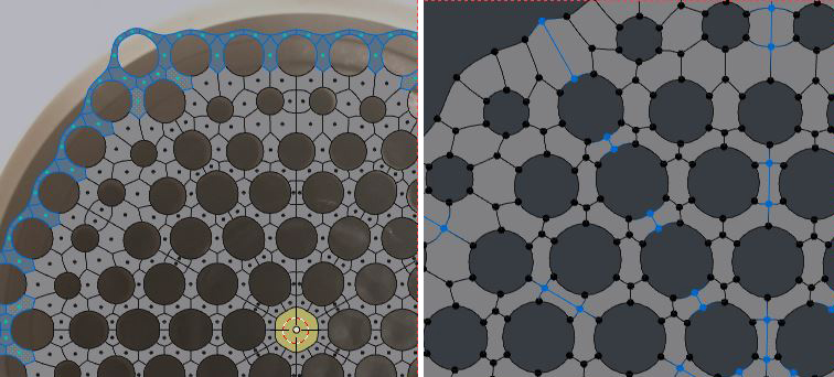
This is a modeling approach to reproducing your reference closely. It's even more work than @internetofmine's, I'm afraid I haven't included all the shortcuts yet..
If you do decide to try it, and get stuck, comment and I'll edit the answer.
Because this is essentially a Sub-D approach, you'll see the illustrations flip between subdivision level 2 (Ctrl 2) and 0 (Ctrl 0), which you do all the time if you work that way.
First, center your reference image. Create a circle. Having Imported the reference as a plane, uniformly scale and move it about until the central hole lines up with the circle. CtrlAltCset the plane's origin to the 3D cursor
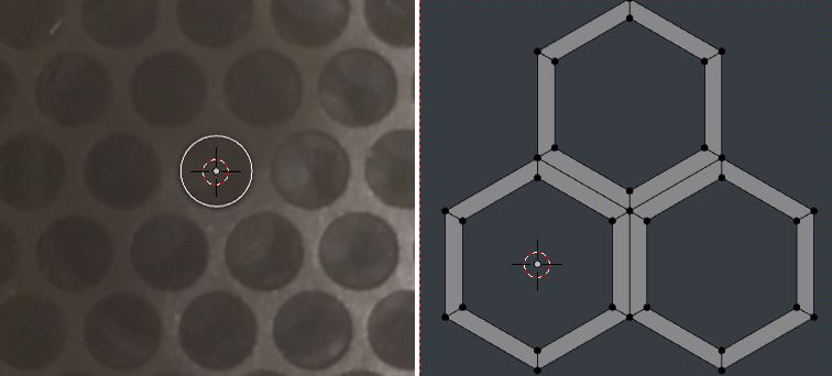
Create another (six-sided) mesh circle with radius 1, Fill, Inset, Delete central face.
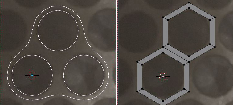
- In edit mode, duplicate the mesh elements twice, snap them together as shown, and remove doubles (Ctrl V > Remove Doubles).
Assign a subsurface modifier level 2, and scaling the reference about the 3D cursor to center the holes, but scaling the holes in the faces with the pivot set to Individual Origins to resize the holes, find the right base-shape for the mesh elements, but still with an outer cell radius of 1.
Now we can switch off the subsurface modifier, and delete a few faces, to leave us with a 2-cell element, suitable for making an array.
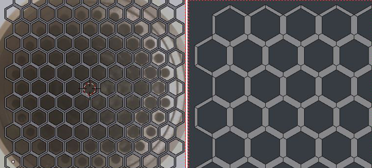
- Assign 2 Array Modifiers, the first is set to a relative offset in X of 2/3 (you can enter the fraction straight into the X field). The second is set to a constant offset in Y of 3. Up the counts to cover the reference holes.
- Alt-Select the outer edges of the original cell rim.
- (After making a duplicate for safety,) apply the array modifiers. The edges should still be selected.
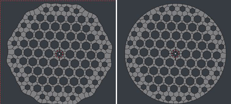
- Dissolve them, and the resulting topology should be as shown. Select the loop corresponding to the central hole, ShiftS > Cursor to selected, and then CtrlAltCset the geometry's origin to the 3D cursor. Now recenter the cursor, and set the geometry's Transform>Location to 0,0,0, and we're all squared up.
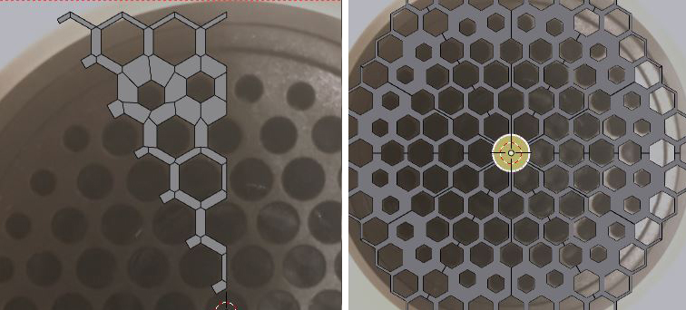
Now (switching your subsurface modifier on and off to help you see, if you need to) in the top 1/3 pf your geometry, select the loops around the smaller holes in the reference, and adjust their size, using Scale with pivot set to Individual Origins. You will need to move the holes a bit, too.
Make 2 cuts with (K)the knife tool. One vertically, point-to point from the central hole, and the other in the 11 o'clock direction constrained to the center of the edges it passes, by holding Ctrl
Ensuring no other edges are selected after the operation, rip the cuts. V
Hover over the geometry outside the wedge, select linked (L) , and delete it, leaving the wedge.
Assign a Mirror modifier (in X) and an Array Modifier with an Object Offset to the wedge. I've brought our measuring-circle back to life to use as the object for the array offset.
Set the array Count to 6, and rotate its offset object in Z by 60 degrees.
- Make sure Merge is checked in both modifiers, including First & Last in the array, and up the merge distance, backing off if you see any change in topology.
Delete any geometry which is not part of the rims of the holes in the reference image.
Select any edges from your cut seams that were not part of the geometry before you made the cuts...
Apply the Mirror and Array Modifiers. The edges you selected in step 17 should still be selected: dissolve them.
Alt Select the perimeter edge-loop, and make it into a circle. I used the built-in add-on 'Loop Tools'>Circle.
The rest is extrusions.
Snappy, this ain't. But it has some techniques I've found useful elsewhere.
-
$\begingroup$ Interesting method, but I as a beginner didn't make it work by this method :) I got stuck in the array section... I will play with it little bit more when I finish this model. Thank You! $\endgroup$ Commented Jul 16, 2018 at 21:29

