2
$\begingroup$

I'm attempting to create a node tree using the Animation Nodes addon to have automatically scaling "Reaction Control System" plumes on any arbitrary mesh.

Essentially, I am hoping to create a single "RCS Plume" object (in my test case, a simple cone), which is then instanced via the object instancer node to occur once per face, with its local z axis facing along the normal of each face. After that, I run the object list of each "plume" through a loop that is supposed to scale each plume depending on the acceleration (currently only rotational, to make things simpler in my test cases), using ClockMender's My-AN-Nodes Object Speed & Acceleration node.

However, I've only been able to get all the plumes to scale the same amounts simultaneously, or to not scale at all. Is this something that's possible with Animation Nodes and Blender?

My attempts so far are:

The uppermost nodes, creating the instances of the cones.

The uppermost nodes, creating the instances of the cones

The nodes being used to calculate the scale when provided the value of one axis on the current, previous, and previous previous frames.

The nodes being used to calculate the scale when provided the value of one axis on the current, previous, and previous previous frames

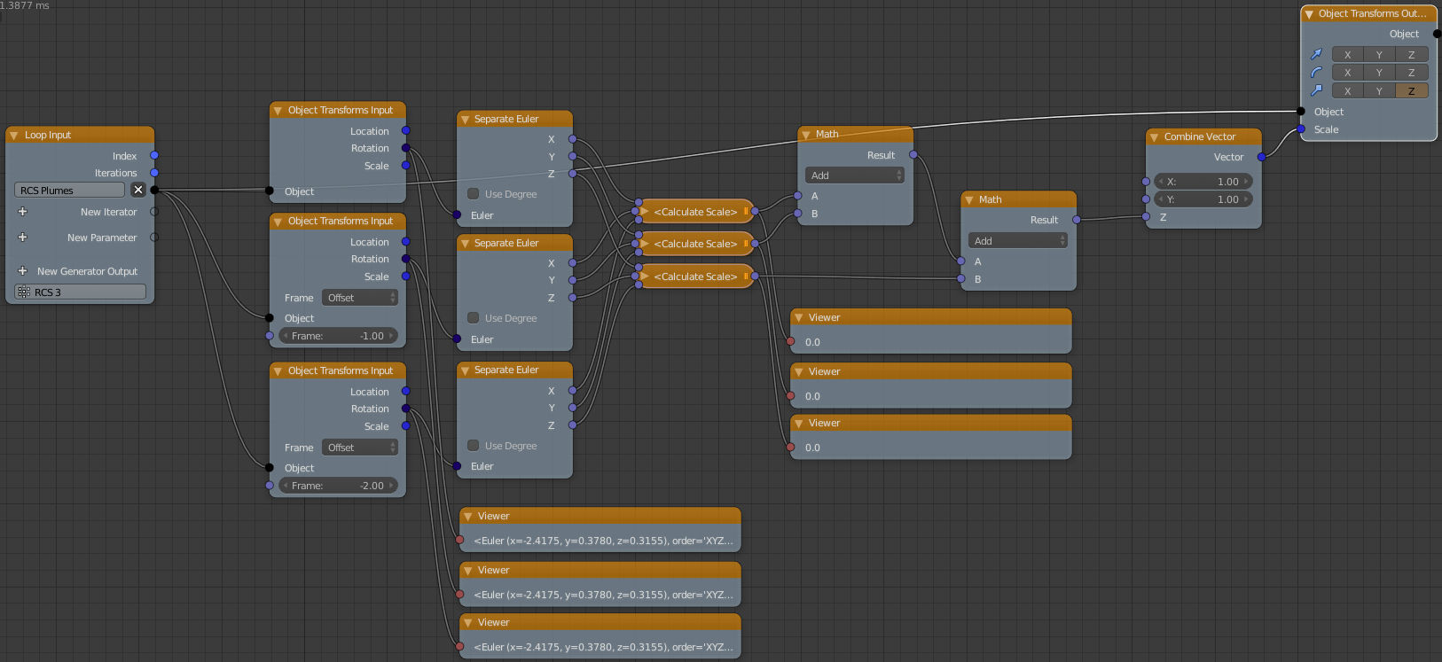
The loop itself, and where I suspect the issue lies.

The loop itself, and where I suspect the issue lies

Specifically, I'm unsure as to why all three object transform inputs are providing the exact same value from their rotation output, given that each should be giving a different frame. (The "Use Current Transforms" option on the two using offsets is unchecked). If instead of giving the loop a object list of each plume, I instead give it the single object that the plumes are being created on, the rotation values are different, as expected. However, this results in the same scaling occurring to each plume regardless of position, as mentioned above.

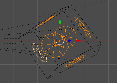
Finally, a view of my test setup:

test setup

The cube is the object that the cones are being created on, and the selected objects are the cones, currently stuck at a local z scale of 0.

My desired result would consist of each cone only scaling when it is tangent (this may be the incorrect term, apologies) to some component of the rotation, and not on the half of the object that is in the direction of motion. Additionally, the scaling would be in proportion to the acceleration, up to cap. Effectively, I would like it to appear as if the cones "firing" are the cause of the rotation, and eventually translation.


Edit 2018-03-11 13:59 EDT: To better explain the effect I'm looking for I've created a small animation manually doing what I'm hoping to do automatically. In the dynamic version I would want a cone to scale to "slow down" the cube on the appropriate/opposite side, rather than it stopping itself.


Edit2 2018-03-13 00:28 EDT:

I've come up with a partial solution, which doesn't fulfill all of my initial requirements, but does come fairly close, and most importantly, looks decent. For reference to anyone looking to implement a RCS animation in blender with animation nodes in the future, who are looking for a (potentially useful) starting point, I've uploaded the file to Blend-Exchange: (Look at NodeTree.001, I forgot to rename it before uploading)

This solution seems computationally heavy, in addition to not being completely physically accurate. It requires each object being instanced to become an RCS plume to have fcurves for translation and rotation. This is accomplished via Animation Nodes' Set Keyframes node, inside a loop.

The RCS effect only fires appropriately for rotation, but if translating and rotating, it will take the translation into account. This can be removed by removing the translational acceleration frame in the nodegroup.

The key to getting only one side to fire, instead of the opposite firing at the same time, was to multiply the scales for each plume by the normals of each face of the base mesh. I've absolutely no idea why this seems to mostly work.

Again, this is not physically accurate, and doesn't take relative position on the base object into account, but hopefully may be useful to someone in the future.

$\endgroup$
11
  • $\begingroup$ What version of AN are you using? Why do you think the problem isn't in your custom acceleration node? It seems it is returning zeros and thus causes the problem? It is a good idea to enable the $x$ and $y$ scales as well because they may be initially zero. $\endgroup$
    – Omar Emara
    Commented Mar 11, 2018 at 15:50
  • $\begingroup$ @OmarAhmad I'm using animation nodes 2.0 (the version posted on July 15, 2017 on JacquesLucke's github). You're correct in that the custom acceleration node is returning zeros, but the reason that it's doing that is because the input it's being fed is the same for each of the frame inputs as far as I can tell. I'm not sure why that's happening as I've set the Object Transform Input nodes to have the appropriate offsets, and when provided a single object, rather than an object list, I do get differing values from the 3 Object Transform Input nodes. Could this potentially be some sort of bug? $\endgroup$
    – Amelia
    Commented Mar 11, 2018 at 16:38
  • $\begingroup$ I am not sure, but frame definition in the Object Transforms Input was removed in the latest version, so I can't test it. How is the animation of your objects defined? Blender animation? if so, I recommend using Evaluate FCurve Node to compute such properties. $\endgroup$
    – Omar Emara
    Commented Mar 11, 2018 at 16:44
  • $\begingroup$ @OmarAhmad Unfortunately, the animation of the cone objects is dependent on the translation and rotation of the cube object, so the cones have no fcurves of their own. Using the fcurve of the cube object results in uniform scaling, in a similar way as to mentioned in the main question as well. $\endgroup$
    – Amelia
    Commented Mar 11, 2018 at 17:21
  • $\begingroup$ But isn't this exactly hat you are trying to do? that is, compute the acceleration data from the rotation data of the cube? $\endgroup$
    – Omar Emara
    Commented Mar 11, 2018 at 17:29

1 Answer 1

2
$\begingroup$

I believe that I've solved the issue. The solution isn't 100% physically correct, but it appears reasonably close with a few caveats:

  • Use Animation Nodes 2.1, no My-AN-Nodes required (this could probably be redone on 2.0)

  • You must also instantiate empties on each location you want a plume, then use the animation nodes Set Keyframes node set to record rotational keyframes for every frame, running entirely through your animation at least once to get that data. (This can be temperamental on Ctrl+Zs, sometimes requiring one to re-keyframe them again)

  • The object/cage you want to have RCS plumes must be reasonably symmetrical for the effect to look good, and be able to have some portion of it (usually all the sections below its center of rotation) covered by an invisible mesh, which determines which half of the object should have the RCS plumes fire in the opposite direction.

  • You must be willing to run a small bit of python code to calculate the acceleration.

  • You may need to tweak the values in Map Range node, depending on the speed and scale of your animation.

  • At this point, this node tree only handles rotational acceleration, not translational acceleration, though it is possible it could be adapted.

  • I am not a mathematician, and may be using any number of these nodes incorrect or only accidentally correct ways.

To start with, you'll want to create 4 objects, an object to be the RCS "plume" (I'd recommend a cone), an empty to calculate individual acceleration on, a "cage" to place the RCS on, and finally, another "cage" to mark which parts of the mesh are the "bottom" half.

Once you've positioned the second cage appropriately, parent it to the RCS cage (or whatever you've parented the RCS cage to). Next, animate the RCS cage in whatever pattern you want. Keep in mind that if you change the animation at all at a later time you'll need to re-keyframe the empties!

At this point, you're ready to create the NodeTree.

Generic support nodes

Start with the generic support nodes, including the script node to calculate acceleration. The python script is as follows:

# Mostly borrowed from https://github.com/Clockmender/My-AN-Nodes/blob/master/speed_acc.py

fps = bpy.context.scene.render.fps

dec_n = DecimalPlaces

if Minus0 == 0 and Minus1 == 0 and Minus2 == 0:
    spd_u = 0
    acc_u = 0
    acc_g = 0
else:
    spd_c = abs(Minus0 - Minus1) * fps
    spd_o = abs(Minus1 - Minus2) * fps
    acc_u = round((spd_c - spd_o) * fps,dec_n)
    spd_u = round(spd_c,dec_n)
    acc_g = round(acc_u / 9.81,dec_n)

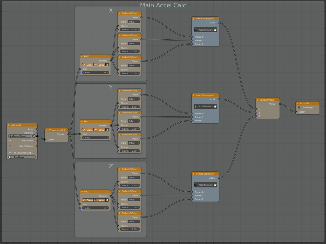
Next, create the loop that'll calculate X, Y, and Z rotational acceleration based on the empties' keyframes.

The node loop that calculates X, Y, and Z rotational Acceleration

Make sure that the the frame offsets are set on the Evaluate FCurve nodes!

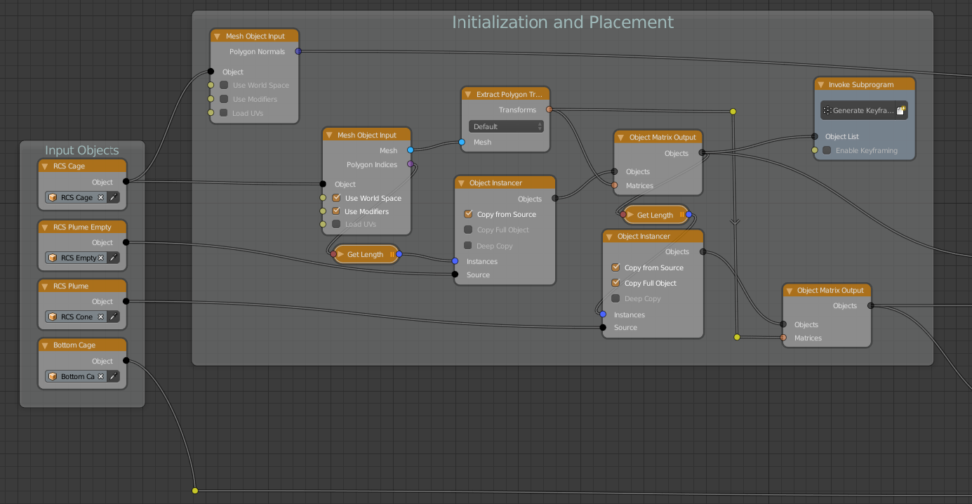
Initialize all the objects and empties.

Initialization and placement of objects and empties

Note that the "Copy Full Object" option for the object instancer for the RCS Cone is likely only necessary if you've fiddled with the object's settings, such as their Cycles Settings.

Next, we grab the BVH tree of the Bottom Cage and check what RCS Cone objects are inside of it.

Calculation of which RCS Cones are inside of the Bottom Cage

We feed this into the List Boolean subprogram we created earlier, as the Boolean Switch node is not vectorized that I can tell. This list of either -1 or 1 gets fed into a Combine Vector node, though I suspect a Vector from Value node would work as well, which is then sent into a scale Compose Matrix, which then feeds into the overall scale calculation.

The nodes that determine how scaled each plume should be on its Z axis

I don't fully understand why the Vector Math Cross operation (of the polygon normals of the RCS Cage, and the acceleration vectors) works in keeping the scaling on "one side" of the mesh, but it does. Next that list of vectors is fed into another support subprogram that uses the Transform Vector node on each pair of vectors and matrices. Next, we separate the vector, add its components, and multiply them by 100 (to get less fractional numbers). The Map Range node determines how far each plume can scale, based on the input (set the input min to 0, and input max to whatever seems a reasonable value based on a viewer node), and the output (set the output min to 0, and the output max to however long you want the maximum length of the plumes to be). Finally, combine that value into a vector and feed it into a Object Transforms Output node with only the Z axis selected, also being fed the list of RCS Cone/Plume objects.

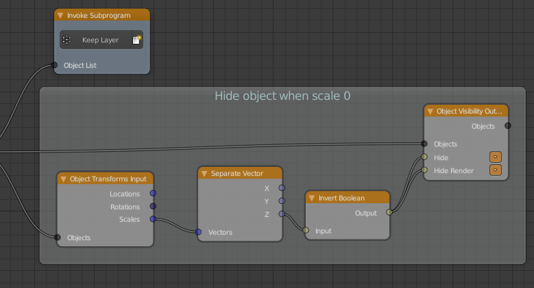
This next part is more cosmetic and QoL than necessity, but it will keep plume objects with a Z scale of 0 from being visible (which can cause z-fighting).

The nodes that control visibility and which layer the plumes occur on

Additionally, the Keep Layer subprogram will make sure that your plumes stay on whatever layer you've selected in the subprogram's body.

For people who'd prefer to have an existent blend file to work with, here's a link:

As mentioned above, you'll need Animation Nodes 2.1

If you've made it this far, congratulations! Here's a 4 second video of the nodetree in action. (The spaceship is not included in the above blend file)

$\endgroup$
1
  • $\begingroup$ I ran out of links in the main answer, due to low reputation, so here's the link to the whole node tree, too zoomed out to be read, but helpful for seeing how the different bits in frames connect. $\endgroup$
    – Amelia
    Commented May 18, 2018 at 11:41

You must log in to answer this question.

Not the answer you're looking for? Browse other questions tagged .