3
$\begingroup$

I am setting up an aluminum material using Blender's internal renderer. It gives me a strange output. I attached 2 screenshots below, one is the render output and the other is the texture settings to achieve the anisotropic effect.
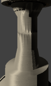
enter image description here

The following image is the texture settings.
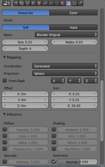
Texture setting to achieve the brushed aluminum effect

If I do an edge subdivision at the spot where the anisotropic effect looks wonky, the wonkiness shifts upwards. What did I do wrong? How should I fix this issue?

EDIT Following @CharlesL ' s comment, I attached a screenshot showing all normals are pointing outside.
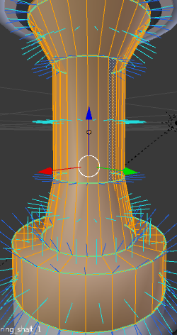
enter image description here

EDIT

This is the .BLEND file for your analysis.

$\endgroup$
4
  • 1
    $\begingroup$ Have you tried recalculating your normals? Enter edit mode then press Ctrl-N. $\endgroup$
    – CharlesL
    Commented Feb 17, 2014 at 23:21
  • $\begingroup$ Yes, I've done that. It is still the same. I've just attached a screenshot in my question above. $\endgroup$
    – ikel
    Commented Feb 17, 2014 at 23:43
  • 1
    $\begingroup$ Would you like to upload the file for easy analysis? $\endgroup$ Commented Feb 18, 2014 at 1:22
  • $\begingroup$ @LeonCheung it is added now. $\endgroup$
    – ikel
    Commented Feb 18, 2014 at 4:38

3 Answers 3

6
$\begingroup$

Tangent shading for BI was introduced in 2.42. According to the feature note:

Using the 'tangent' option in the Material → Shaders panel alters the direction of shading to use the tangent vectors, giving anisotropic shading for any of Blender's diffuse and specular shaders. This is useful for creating brushed metal or wood, where the microscopic grooves in the material give highlights that follow a direction, rather than just being circular.

Currently, Blender uses a mesh's UV co-ordinates to define the direction of the shading (along the V axis). This means that models must be UV unwrapped to take advantage of tangent shading.

So, an expected anisotropic result needs UV coordinates to know which direction the light should stretch. To be exact, the anisotropy will stretch the light vertically along the UV coordinates.

enter image description here

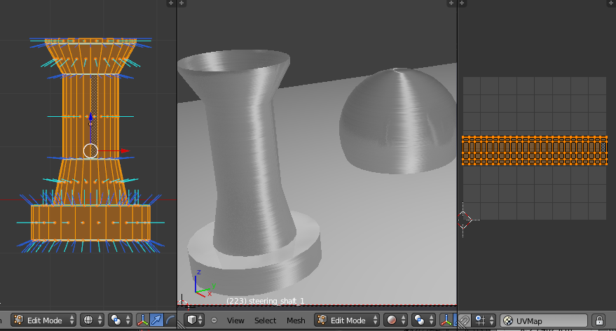
For the attached case, You can unwrap it from the side view with UV unwrap methods like Cylinder projection, which is usually recommended. Besides, using UV as the Coordinate type in Texture setting is the better choice as well.

$\endgroup$
2
$\begingroup$

You should UV-unwrap your model. I suggest to apply a cylinder projection from the front ortographic view. The UV also controls the anisotrophic direction.

Otherwise the tangent is calculated based on the normals. Where te interpolation of the face normals is near to z = 0 the tangent calculation gets numerically instable and I think the tangent also gets negated there. At least it seam so, but I am not sure how Blender calculates tangents based on normals.

$\endgroup$
0
$\begingroup$

I would strongly suggest you use cycles for this, because there that sort of issue isn't a problem. Afaik this error could be caused by lighting. I forgot how the effect is called, but if you have too few light sources in "old" raytracing, you can end up with quads "split", meaning one tri gets light only from one light source, the other only from the second lamp, and you can see a "seam". Have you tried adding a hemi to your scene?

$\endgroup$

You must log in to answer this question.

Not the answer you're looking for? Browse other questions tagged .