12
$\begingroup$

I'm currently working on a model of an X-wing that I'm intending for use in a game and running into a bit of trouble with the shading of the mesh. The upper nose is rounded off where the sensor cone attaches, but at the point it reaches the canopy frame it flattens out and meets at a corner.

Everything is fine and dandy when the sides are modeled:

enter image description here

but once I close it off and add the top of the nose, the shading goes to hell:

enter image description here

As you can see, the smoothing gets confused at the lip of the cockpit.

I've tried a couple different means of getting around this, none of which looks right while maintaining the correct shape. The transition from the rounded to flat is a fairly important part of the ship's character, so I don't want to discard the contours, either.

Any tips or suggestions on modeling this area?

Addendum:

If I eliminate that second angle where the canopy frame meets the fuselage as marked in red:

enter image description here

this also fixes the smoothing. However this is not a solution, as the angle is a part of the design. It DOES give me another thought on fixing, but I won't be able to test it until I get home.

$\endgroup$
2
  • 1
    $\begingroup$ After writing an answer and editing the title I noticed that this is arguably a duplicate of blender.stackexchange.com/questions/734/… but I think it's ok to have a more general answer for this. $\endgroup$
    – iKlsR
    Commented Jan 22, 2015 at 6:42
  • $\begingroup$ Normals>Average (after recalculating outside if needed) if all else fails, also check for overlapping verticies/edges/faces, join whenever you can, mark sharp edges sometimes helps but generally that should work on its own. And of course, if they look backwards after the fact just flip them. Generally what happens is faces get mucked up from adding in angled edges where a flat plane once was, average usually fixes this without fail. Always APPLY all transformations before doing anything like bevels, etc. $\endgroup$ Commented Jun 22, 2023 at 21:07

2 Answers 2

15
$\begingroup$

This is because your mesh edges change direction sharply. It's unavoidable by default unless you add supporting geometry to make the transition smoother.

The image below shows 3 similar cylinders that were smooth shaded. The first has a ngon capping the top, the second is capped with triangles and the last has a ngon cap but has a bevel around the edge. Notice that the 3rd cylinder doesn't have any weird shading since we eliminated the sharp edge.

enter image description here

So to fix, add supporting geometry by beveling your edges to avoid sharp curves and turns.

Another fix is to just add an Edge Split modifier. The cylinder on the left is the default one shaded smooth, the other one has the modifier. This won't always just work out of the box though for more complicated shapes and might require some tweaking.

enter image description here

$\endgroup$
7
  • $\begingroup$ I already have the Edge Split modifier applied. I've also tried adding a bevel and I just haven't found a way to do that that doesn't alter the shape too much. $\endgroup$
    – Ambaryerno
    Commented Jan 22, 2015 at 12:44
  • $\begingroup$ @Ambaryerno Share the model so we can have a look at it. $\endgroup$
    – iKlsR
    Commented Jan 22, 2015 at 23:35
  • $\begingroup$ Mesh is here: wyrmfyrforge.net/Uploads/X-Wing_FuselageTrouble.blend I've removed out everything but the offending section for size and simplicity. $\endgroup$
    – Ambaryerno
    Commented Jan 23, 2015 at 0:44
  • 1
    $\begingroup$ @Ambaryerno This is because of pinching, you can't have that many points ending at one pole in space and not expect any artefacts. The tris are causing that. rework them and it should smooth out. $\endgroup$
    – iKlsR
    Commented Jan 23, 2015 at 2:58
  • $\begingroup$ I made a few adjustments and got it to a point where it didn't require a significant reworking of the mesh around the cockpit. Since the canopy is all hard edges, anyway, cheating by marking a couple extra sharp edges to maintain the shading was much less noticeable there. Thanks for all the feedback. This is proving a more and more complex build the more clear references I find. :-P $\endgroup$
    – Ambaryerno
    Commented Jan 23, 2015 at 3:06
4
$\begingroup$

As mentioned by iKlsR, this is caused by blender trying to smooth the normals over a sharp edge.

To avoid this, you can also use split normals. Split normals behave basically like the edge split modifier, but without actually splitting edges and creating double vertices.

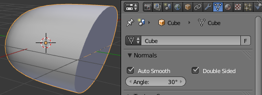
To use it, enable Autosmooth in Properties > Object Data > Normals and tweak the Angle as you would with an edge split modifier:

enter image description here

You can also manually mark specific edges, vertices, or faces to be sharp:

enter image description here

$\endgroup$
2
  • $\begingroup$ The problem is when I try to mark a vertex as sharp, it applies it to the ENTIRE edge (and in fact, ALL edges that touch that vertex) even when I only select a single vertex to mark. Autosmooth I run into the same issue: When tweaking the angle, it turns the entire edge sharp, not just the vertex. $\endgroup$
    – Ambaryerno
    Commented Jan 22, 2015 at 12:48
  • $\begingroup$ For what it's worth (blender v3.4) I found that using Normals>Average face area fixed all my problems with the "creasing" effect you get when adding varied angles of sharpness to an object, such as going from/to a bevel from a flat surface, or areas where mesh transforms have been used heavily. This is my go-to fix for most of those problems--an artist should never have to manually edit surface normals themselves, nor should they have to go through and select every edge unless they are making some object that defies the laws of known reality. Note this does not include normal "trickery". $\endgroup$ Commented Jun 22, 2023 at 20:22

You must log in to answer this question.

Not the answer you're looking for? Browse other questions tagged .