8
$\begingroup$

I have a plane with a texture with both transparent and opaque elements. I would like to give that texture thickness. If I solidify the plane, the texture is only on the faces, not 'through' the solidified plane. I could apply array modifier in very tiny increments to build the thickness, but that's not optimal and seems not really smart either.

UPDATE: More details:

My initial request for this project: Is it possible to convert image texture's black color to transparent?

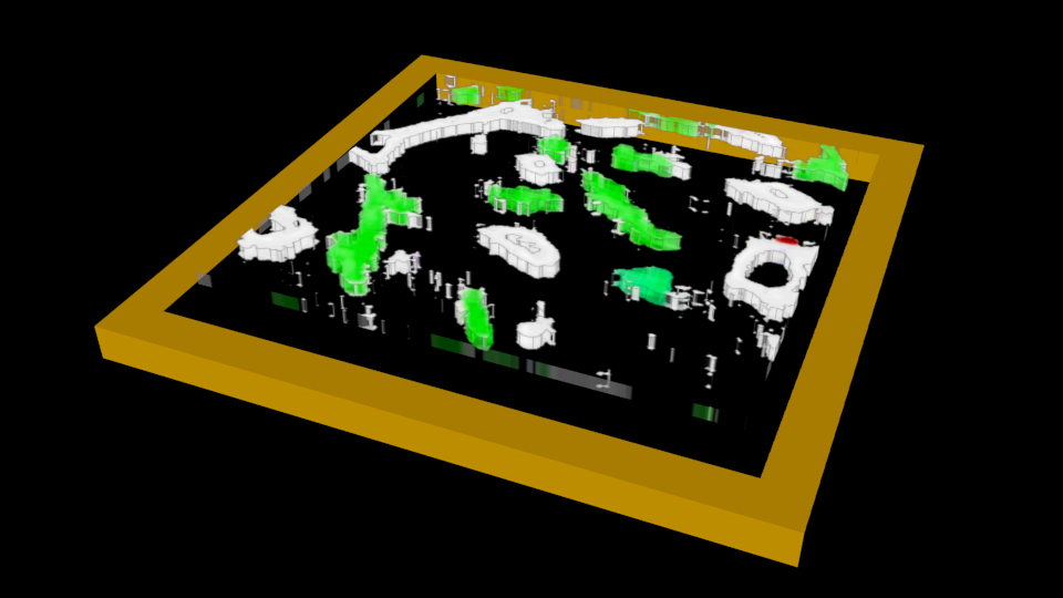
I am trying to recreate series of confocal microscopic images into 3D structures. Each image is flat, I tried to give them thickness by adding array of 6 planes but it looks awful. If I could give each plane thickness, they would stack in nice 3D shapes.
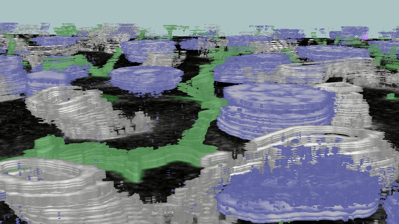
enter image description here

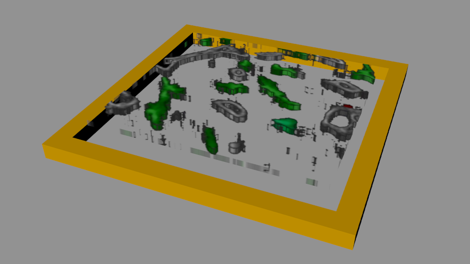
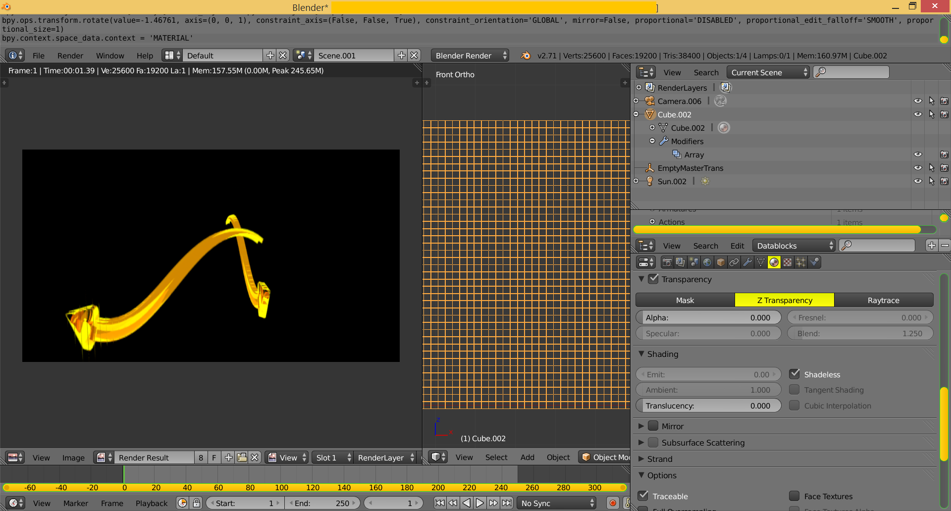
UPDATE 2 David - I tried your suggestion, but I'm getting no effect after displacement. I added solidify modifier on top of that, but I only get fill on edges / rims:
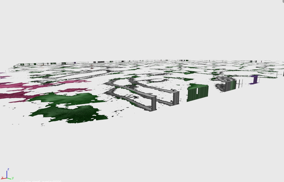
enter image description here

FINAL UPDATE: I followed atomicbezierslinger method - it gave me pretty decent results with very good 3D reconstruction. I used 100x100 cubes per picture, resized z-size to 0.2. Attached is a render of 13 z-stacks from confocal. I need to tweak noise a bit, but I guess there's no better way to go. Now I need to write a Python code to automate it - each data set is 100 z-stacks - too much to do it by hand. I appreciate all suggestions and your help.
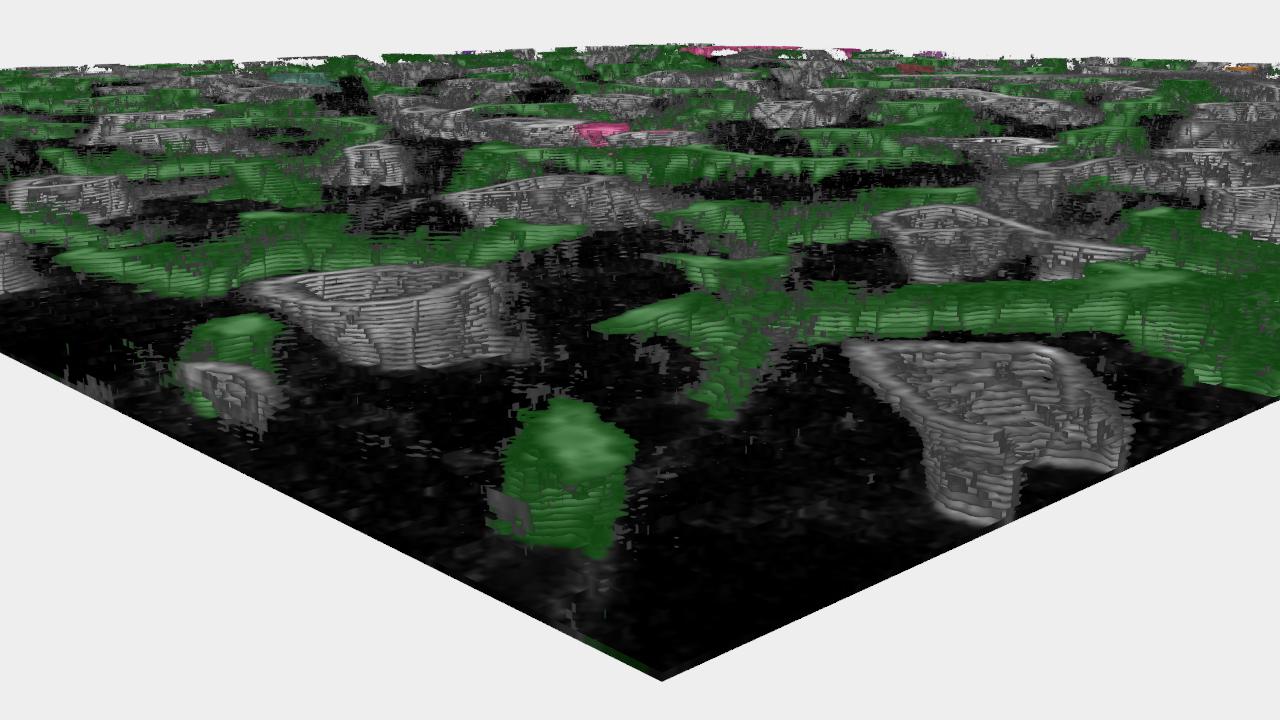
enter image description here

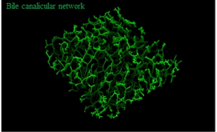
FOLLOW UP: I probably was unclear asking initial question and didn't explain my goal well. Confocal microscope uses laser to scan fluorescent-labeled animal tissue. Each laser pass reads a plane of ~1 micron thickness then, the next scan goes deeper and deeper. This way z-stacks are created. There is a software for 3D reconstruction of z-stacks (e.g. ImageJ) but I am exploring possibilities and limitations of Blender in this application. Please see below image for the explanation.

Picture source: Hammad et al., Arch Toxicol (2014) 88:1161–1183
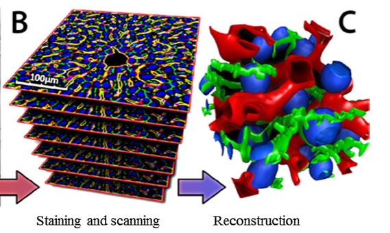
enter image description here enter image description here

$\endgroup$
6
  • $\begingroup$ Cycles Render or Blender Render? $\endgroup$ Commented Oct 7, 2014 at 17:37
  • $\begingroup$ Are you using volumetrics? How would the texture be visualized "through" the plane? $\endgroup$
    – gandalf3
    Commented Oct 7, 2014 at 17:56
  • $\begingroup$ Related: blender.stackexchange.com/q/5849/599 $\endgroup$
    – gandalf3
    Commented Oct 7, 2014 at 18:03
  • $\begingroup$ Cycles. No volumetrics. $\endgroup$
    – marcheenek
    Commented Oct 7, 2014 at 19:39
  • $\begingroup$ In that case I think you are better off tracing around the shapes with a mesh or curve object and extruding that. $\endgroup$
    – gandalf3
    Commented Oct 7, 2014 at 20:01

5 Answers 5

8
$\begingroup$

Voxels

Consider some images where the planes (rectangles) are either parallel or pependicular .. based on cubes. Flat Surface on Top.

  • Small Sample of Color Transparency Threshold

enter image description here

  • Small Sample of High Density Mesh from distorted image from user provided image from natural light camera. Image below.

enter image description here

  • Sample from artificial image with more precise edges. Image below.

enter image description here

Steps

  • Create a high density mesh with cubes. Simple Cube (6 sides) with the 2 array modifiers, vertical Z (1) and horizontal X (1), repeat 40 or more on both, then apply both. (I suggest user use a high number 500 or more if possible)Vertex Remove Doubles. See image above. The number 40 was for a quick test.
  • UV Project . Turn specularity to zero. Add your texture. Affect color and transparency.
  • Render

Observations

  • High Density Mesh. Sheet of cubes. Geometry modified. One mesh of many cubes internally. High Density Mesh is the same requirement for Displacement in texture panel. See below.

  • Please Improve. I used a visible margin for each cube in the original array modifier, in the example below. You can have zero margin. Thus some lines in interior.

  • The more intricate the transparency the more need for density with this technique.
  • The texture below has .png transparency. Careful image processing is necessary and the best image, or least offensive image, here can be improved.

The perceived thickness is determined by the alpha of the channel. Your can change transparent image or image sequence. with no further work. No particular modelling. There are other ways to do this. Quick example. I have added an array modifier only to show you two views at once. Front and Side. Any undesirable details have not been investigated.

enter image description here

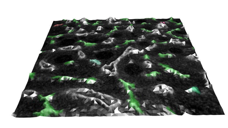
Displacement method. Dense mesh from a plane subdivided. Texture affecting displacement. There is no flat surface. This technique is documented many places. This may be the least suited to your purposes. Consider Subdivision Modifier. The image also shows the triangulated surface just for discussion purposes.

enter image description here

All the above should be adjusted to you tastes.

Optionally consider a particle system with the

  • Texture determining [density].
  • Texture determining [color] in emitter.
$\endgroup$
2
  • $\begingroup$ Displacement is not an option - 3D reconstrucion comes from series of z-stacks, not single image. Good use of displacement anyway! $\endgroup$
    – marcheenek
    Commented Oct 8, 2014 at 16:25
  • $\begingroup$ Thanks for leading me into this little sporadic spelunking. Its entertaining in the free time. Please clarify your problem statement in your original question. All clarifications should go there. It is grand when you help us to understand. Close to zero people will read it here. Please clarify and be complete. $\endgroup$ Commented Oct 8, 2014 at 16:48
3
$\begingroup$

Here's a brutal version of the voxel solution some people have suggested: http://web.purplefrog.com/~thoth/blender/python-cookbook/thicken-texture.html. Performance is going to be horrible, but it seems to work when I use the sapling_jungle.png from minecraft.

Here's a copy in-line in case the hyperlink isn't working:

import bpy
import bmesh

class VertexAccumulator:
    # use this class when you can't come up with a good deterministic numbering scheme for your vertices.

    def __init__(self):
        self.verts_ = []
        self.vertIdxs = {}

    def keyFor(v):
        return "%f,%f,%f"%(v[0], v[1], v[2])

    def idxFor(self, v):
        key = VertexAccumulator.keyFor(v)
        rval = self.vertIdxs.get(key)
        if None==rval:
            rval = len(self.verts_)
            self.vertIdxs[key] = rval
            self.verts_.append(v)
        return rval

    def verts(self):
        return self.verts_

def getAlpha(img, x, y):
    w,h = img.size
    if x<0 or x>= w or y<0 or y>=h:
        return 0
    o = x + y * w
    return img.pixels[o*4+3]


def addFaceAndUV(verts, faces, uvs, va, width, height, uv_adj_x=0, uv_adj_y=0):

    faces.append([ va.idxFor(v) for v in verts])

    uvForFace = [ [(v[0]+uv_adj_x)/width, (v[1]+uv_adj_y)/height] for v in verts ]
    uvs.append(uvForFace)


def addFaces(x, y, width, height, faces, img, uvs, va):
    a = getAlpha(img, x, y)
    if (a > 0):
        addFaceAndUV([[x, y, 0],
            [x + 1, y, 0],
            [x + 1, y + 1, 0],
            [x, y + 1, 0]], faces, uvs, va, width, height)

        addFaceAndUV([ [x, y, -1],
                  [x, y + 1, -1],
                  [x + 1, y + 1, -1],
                  [x + 1, y, -1] ], faces, uvs, va, width, height)

        if getAlpha(img, x - 1, y) <= 0:
            addFaceAndUV([[x, y, 0],
                [x, y +1, 0],
                [x, y +1, -1],
                [x, y, -1],], faces, uvs, va, width, height, 0.01, 0)
        if getAlpha(img, x + 1, y) <= 0:
            addFaceAndUV([[x + 1, y, 0],
                [x + 1, y, -1],
                [x + 1, y + 1, -1],
                [x + 1, y + 1, 0],], faces, uvs, va, width, height, -0.01,0)

        if getAlpha(img, x, y - 1) <= 0:
            addFaceAndUV([[x, y, 0],
                [x, y, -1],
                [x + 1, y, -1],
                [x + 1, y, 0],], faces, uvs, va, width, height, 0, 0.01)

        if getAlpha(img, x, y +1) <= 0:
            addFaceAndUV([[x, y + 1, 0],
                [x + 1, y + 1, 0],
                [x + 1, y + 1, -1],
                [x, y + 1, -1],], faces, uvs, va, width, height, 0, -0.01)


def makeMeshForImage(img, name):
    width,height = img.size
    print (height)

    va = VertexAccumulator()
    faces = []
    uvs = []

    for y in range(height):
        for x in range(width):
            addFaces(x, y, width, height, faces, img, uvs, va)

    mesh = bpy.data.meshes.new(name)
    mesh.from_pydata(va.verts(), [] , faces)

    apply_UVs(mesh, uvs)

    set_preview_tex(mesh, img)

    return mesh


def apply_UVs(mesh, uvs):
    # add a UV layer called "spiral" and make it slanted.
    mesh.uv_textures.new("simple")
    bm = bmesh.new()
    bm.from_mesh(mesh)

    uv_layer = bm.loops.layers.uv[0]

    nFaces = len(bm.faces)
    for fi in range(nFaces):
        x0 = fi*2/nFaces
        x1 = (fi+1)*2/nFaces
        for j in range(len(uvs[fi])):
            bm.faces[fi].loops[j][uv_layer].uv = uvs[fi][j]
    bm.to_mesh(mesh)

# put the image behind the UV layer for the times when you're using the Multitexture shader on the 3D view.
def set_preview_tex(mesh, img):
    bm = bmesh.new()
    bm.from_mesh(mesh)
    tl = bm.faces.layers.tex.active
    if tl:
        for f in bm.faces:
            f[tl].image = img
    bm.to_mesh(mesh)

def material_for(img):
    rval = bpy.data.materials.get(img.name)

    if rval is None:
        tex = bpy.data.textures.new(img.name, 'IMAGE')
        tex.image = img
        tex.use_interpolation=False
        tex.filter_type = 'BOX'

        rval = bpy.data.materials.new(img.name)
        rval.texture_slots.add()
        rval.texture_slots[0].texture = tex
        rval.texture_slots[0].texture_coords = 'UV'
        rval.texture_slots[0].uv_layer = 'simple'

    return rval

def makeObjForImage(img, name):
    mesh = makeMeshForImage(img, name)
    obj = bpy.data.objects.new(name, mesh)
    w,h = img.size
    obj.scale = [1.0/w, 1.0/h, 1.0/w]

    mesh.materials.append(material_for(img))

    return obj

img = bpy.data.images["sapling_jungle.png"]
obj = makeObjForImage(img, img.name)
scn = bpy.context.scene
scn.objects.link(obj)
scn.objects.active = obj
$\endgroup$
2
$\begingroup$
  1. Use the add images as planes add on to add your image.
  2. Subdivide the plane about 30 times. Tab in to edit mode W > Subdivide. Adjust the Number of Cuts in the tool shelf, or by pressing F6.
  3. Add a Subdivision Surface modifier set to Simple.
  4. Add a Displace modifier set the Texture Coordinates to UV and add a new texture. Go to the texture tab, use the same image texture for the displace modifier's texture.
$\endgroup$
1
$\begingroup$

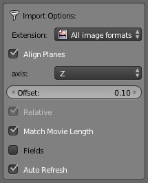
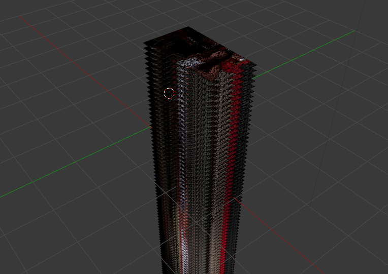
There is a modified version of the Import Images as Planes add-on that lets you stack series of images on a determined axis and determine the offset.

enter image description here

enter image description here

The script can be found HERE

The full thread on blenderartists.org

NOTE: Keep in mind that is a modified version of the original script so you might need to move the original out of the scripts folder so that blender doesn't complaint of having multiple add-ons with the same name.

$\endgroup$
0
$\begingroup$

It is not really possible to give a texture thickness. Geometry is basically a collection of points (vertices) in space, vertices are connected with edges, and edges are filled with. Faces have no thickness, they simply reflect photons (rays). Textures are for modifying the color (or direction) of rays that hit the face. To create a solid object you have to model it. I would use your texture as a background image and model the object using the texture as a reference.

$\endgroup$

You must log in to answer this question.

Not the answer you're looking for? Browse other questions tagged .