6
$\begingroup$

Here is a handy mobius strip. Mathematically it has one surface, but in Blender it's just a twisted flat mesh stitched together carefully. I added some icospheres as breadcrumbs to guide the eye. I am going to try to add some patterning to the "surface", either a color gradient or a UV-map in the future.

But, right now, I am wondering if using backfacing in nodes as @BenSimonds shows in the second answer here is going to be robust, or if I should just get used to making my 2D surfaces as really thin 3D double-surfaces (e.g. a flattened tube in this case) and avoid any potential future problems. There may be some experience out there about things that can go wrong here that I can't find with google.

Note: surfaces will be pretty complicated, and making them thin 3D shapes will be tricky - this is a simple example for discussion.
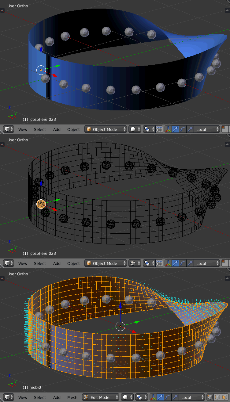
blueish mobius strip

import numpy as np
import bpy

R,   W  = 2.0, 1.0
nth, nw = 120, 9

th = np.linspace(-0.5*np.pi, 1.5*np.pi, nth+1)[:-1][:,None]

w = np.linspace(-0.5*W, 0.5*W, nw)[None,:]

phi = 0.5*np.pi*np.cos(th.clip(0.0, np.pi))

x = (R + w*np.cos(phi)) * np.cos(th)
y = (R + w*np.cos(phi)) * np.sin(th)
z = (0 + w*np.sin(phi))

nx = np.cos(th)*np.sin(phi)
ny = np.sin(th)*np.sin(phi)
nz = -np.cos(phi)

verts0 = [tuple(thing) for thing in zip(x.flatten(), y.flatten(), z.flatten())]
faces0 = []

for ith in range(nth-1):
    for iw in range(nw-1):
        v1 = nw*ith + iw
        v2 = v1 + 1
        v3 = v2 + nw
        v4 = v3 - 1
        faces0.append((v1, v2, v3, v4))

for iw in range(nw-1):
    v1 = nw*(ith-2) + iw
    v2 = v1 + 1
    v3 = nw*0 + nw-2 - iw # last one is sideways 'cause it's a mobius!
    v4 = v3 + 1
    faces0.append((v1, v2, v3, v4))

blueish = bpy.data.materials.new("BLUEISH")
blueish.diffuse_color = (0.1, 0.3, 1.0)
blueish.specular_color = (200, 1.0, 100) # CHANGE THIS!

mobi_mesh_0 = bpy.data.meshes.new('mobi0')
mobi_obj_0 = bpy.data.objects.new('mobi0', mobi_mesh_0)

bpy.context.scene.objects.link(mobi_obj_0)
mobi_mesh_0.from_pydata(verts0, [], faces0)

mobi_obj_0.active_material = blueish

bpy.data.objects['mobi0'].select = False
bpy.data.objects['mobi0'].select = True

bpy.ops.object.shade_smooth()

d = 0.11
for i in range(0, nth, 5):
    xp = x[i,4] + d*nx[i]
    yp = y[i,4] + d*ny[i]
    zp = z[i,4] + d*nz[i]
    q = bpy.ops.mesh.primitive_ico_sphere_add(size=0.1, location=(xp, yp, zp))
$\endgroup$
3
  • $\begingroup$ Did you figure out what you're going to do? This type of complex geometry is interesting to me even though it is so darn confusing. You asked how to make "a different color each side" which is a bit of a conundrum since you're dealing with a one sided surface. By adding thickness you can fix the seam caused by the normals flipping, but even then, it's still a one sided continuous loop. Where does 'Side A' become 'Side B'? $\endgroup$
    – YoeyYutch
    Commented Jul 28, 2015 at 0:40
  • $\begingroup$ Good catch @YoeyYutch! I was getting ahead of myself with the title. What I want to do next is (and I don't know the correct mathematical term) double the surface. At each point on the Mobius, create two new points slightly displaced on either side perpendicular to the surface. All these points together, I am told, when unfolded, will be an orientable surface - an annulus, or a belt with a whole-twist. I can't wait to find out which! $\endgroup$
    – uhoh
    Commented Jul 28, 2015 at 5:21
  • $\begingroup$ Glad to hear you haven't given up! I actually made my comment primarily to gauge whether or not you are still actively working on this before posting an answer. While my answer is by no means a perfect solution, you may find some elements helpful. Let me clean up my blend file and write up some details. If I haven't posted it within the next half hour, I'll have it up sometime this evening. $\endgroup$
    – YoeyYutch
    Commented Jul 30, 2015 at 11:42

1 Answer 1

2
$\begingroup$

The following example accomplishes two things that I believe you want to accomplish based on your question.

  1. Eliminate the seam caused by the one sided surface.
  2. Highlight the twisting contours of the mesh so that the viewer can more easily understand it.

Here is the result: enter image description here

Here is what I did. Once I created a mesh that closely resembles your picture, I used the Solidify modifier. The resulting mesh had a squashed seam where the geometry flipped through itself. I then had to apply the modifier so I could delete those faces and reconnect them to fix the seam.

At this point I unwrapped it using the 'Reset' option, so each face filled the texture space. This worked well for the most part, but I had to do a bunch of cleanup. Many of the face normals needed to be flipped and/or rotated 90 degrees. This wouldn't have been as much of a problem if I had used a larger offset in the Solidify modifier. The opposing faces were so close to each other that it was difficult to make selections. In hindsight, I should have unwrapped the mesh before connecting the loop to avoid this problem altogether.

The material is pretty basic. I think the key to getting a uniform texture without distortion is to use the Reset method of unwrapping. However this is only true for tileable textures. I used the Brick Texture here. Checker also works or you could create your own. It may be possible to make an organic texture work using Generated Texture Coordinates, which I tried, but I didn't know how to correct the distortion on the twisted section.

I liked how the Brick texture worked because when you use it as the 'Factor' for a Mix between Emission and Transparency, you can play with the settings so that the texture for each face becomes asymmetric, allowing the grid on the opposing face to become visible. If you really want to impress the ladies, try using a MixRGB node between two Brick Textures.

I settled on this material, because it is pretty simple and just by playing with the sliders in the Brick settings or plugging different inputs from the Geometry node into the Emission strength and color can produce a lot of variety depending on the look you want.

$\endgroup$
5
  • $\begingroup$ That's quite beautiful @YoeyYuch! So when I said "or if I should just get used to making my 2D surfaces as really thin 3D double-surfaces (e.g. a flattened tube in this case) and avoid any potential future problems." I meant that I would just write the script to make a thin, flat tube in the beginning. That's just 2-3 more lines in the script. I want to avoid use of GUI since I'll be animating. I'm wondering if I make the "normals-out" side one color, and the other side another color, will there be problems. I'm happy with a seam that changes color, but not the false shadow in the image $\endgroup$
    – uhoh
    Commented Jul 31, 2015 at 4:55
  • $\begingroup$ So imagine first a solid blue on the "front side" (normals-out) and a solid red on the backfaces. The seam would be a color-step. That's OK. Then imagine a red-purple-blue-cyan color gradient along the "front" (normals-out) side and a cyan-green-yellow-red gradient along the "back". That would show no seam. It would show a "color wheel" that takes two complete turns around the mobius to cycle through all colors. $\endgroup$
    – uhoh
    Commented Jul 31, 2015 at 5:07
  • $\begingroup$ So this is obviously becoming a new question. I will post a new one and add a link to it. $\endgroup$
    – uhoh
    Commented Jul 31, 2015 at 5:12
  • 1
    $\begingroup$ Hey thanks. Glad you like it. I didn't expect that this would be exactly what you wanted, but it seems to have stirred up some new ideas which is kind of what I was aiming for.... Yep I hear what you're saying about the color wheel. I think that's a good idea. . In that case you will want to make the UV map with a single 'island' instead of using the 'Reset' option. If you use a Gradient Texture followed by a Color Ramp node into your shader, you'll have a lot of control over the color spectrum. Like you said you just start and end with the same color and you're in business... $\endgroup$
    – YoeyYutch
    Commented Jul 31, 2015 at 5:42
  • 1
    $\begingroup$ You'd also get additional color control with a ColorRamp that I think would be helpful for visually describing the twisted regions. I was at the mercy of the normals. On a side note, the mesh I made has no thin faces connecting the two halves. if that makes sense. In other words, it's not a tube. Its so weird. I was trying to wrap my head around the fact that you could slide a knife in between the faces and run it all the way around, as if it were two separate pieces, but then unravel it to become one continuous loop. Magic I tell ya. Ooh getting late. I'll probably have loopy dreams now. $\endgroup$
    – YoeyYutch
    Commented Jul 31, 2015 at 6:02

You must log in to answer this question.

Not the answer you're looking for? Browse other questions tagged .