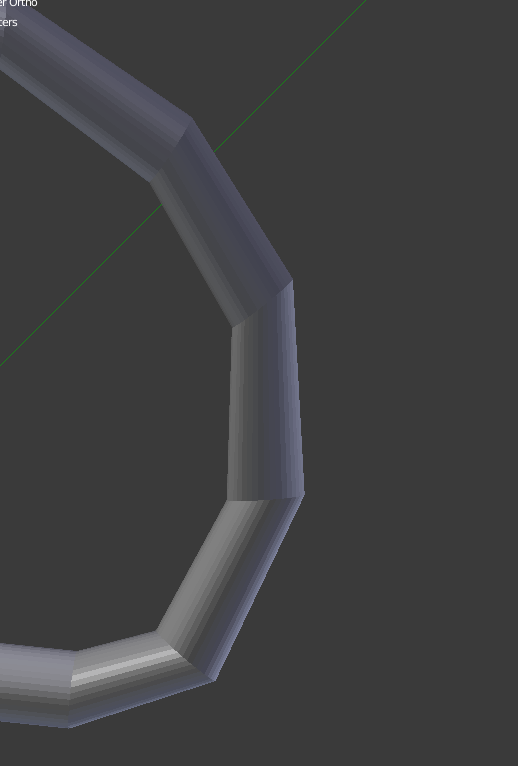
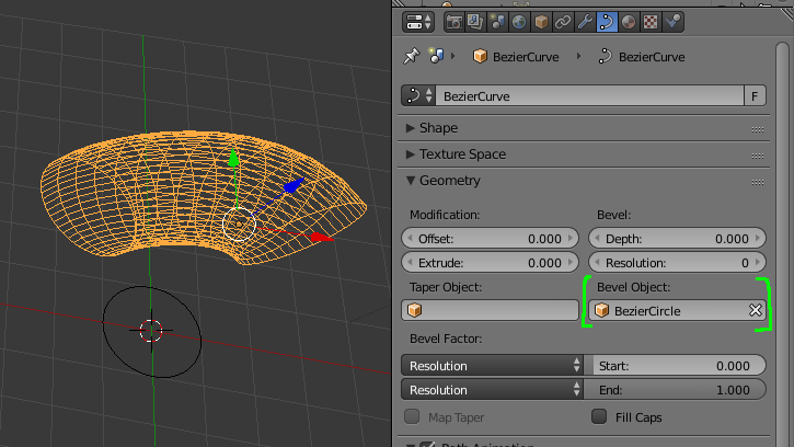
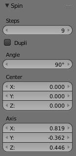
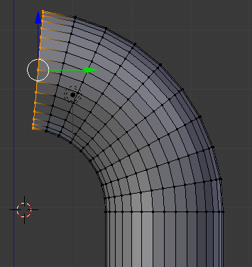
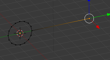
One way to do this is rather than modeling the segments of the cord, to model the joints between the segments, and fill in between the joints by bridging the edge loops at the joints. Suppose the goal is a cord of 16 cylinders. Create an open circle with 16 vertices, and the desired radius, then adjust it to the desired orientation. Then pick one vertex, and extrude it away from the circle. The result looks like this:
Now to make your cord, make sure "Mesh:Loop tools" is activated, and set the pivot point to "active element". Duplicate the cord tool, and rotate it about the anchor point. When you get the two instances of the cord tool where you want them to be relative to location and rotation, as, for ecample in
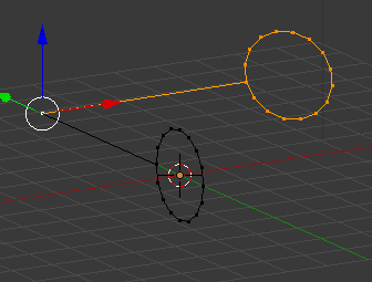
select the vertices of the circles on both cord tools and from the edges menu (CTRL-Ekey), select the "bridge edge loops option.
This is the result.
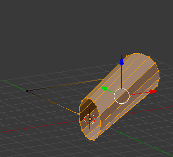
Now the diameters of the places where the cylinders meet are all the same.
If the overall appearance of the cylindrical object is not quite what you would like, one easy way to adjust this is to add another circle at the point where it is least satisfactory.
Sometimes on an object like this, I'll make it away from the point which is its intended final location. Making use of this method means I can select all of the anchor points, and conveniently move the entire assembly to where I want it to go. After the I'm done with the assembly, I delete the anchor points.
Another technique is to make a short section of your cylinder, but instead of extruding the end, duplicate (SHFT-Dkey the section, and move it to the position of the second segment. Now add an empty object at the location of the center of the arc formed by the two segments, plus the intervening empty section. Rotate the inside ends of the two cylinder segments slightly, and again use the bridge loop to make the segment joining the two.
One common factor in both of these techniques is to keep the sections of the cord short, and the angles of the joint between the two as close to perpendicular to both of the axes of the cylinders as possible.
