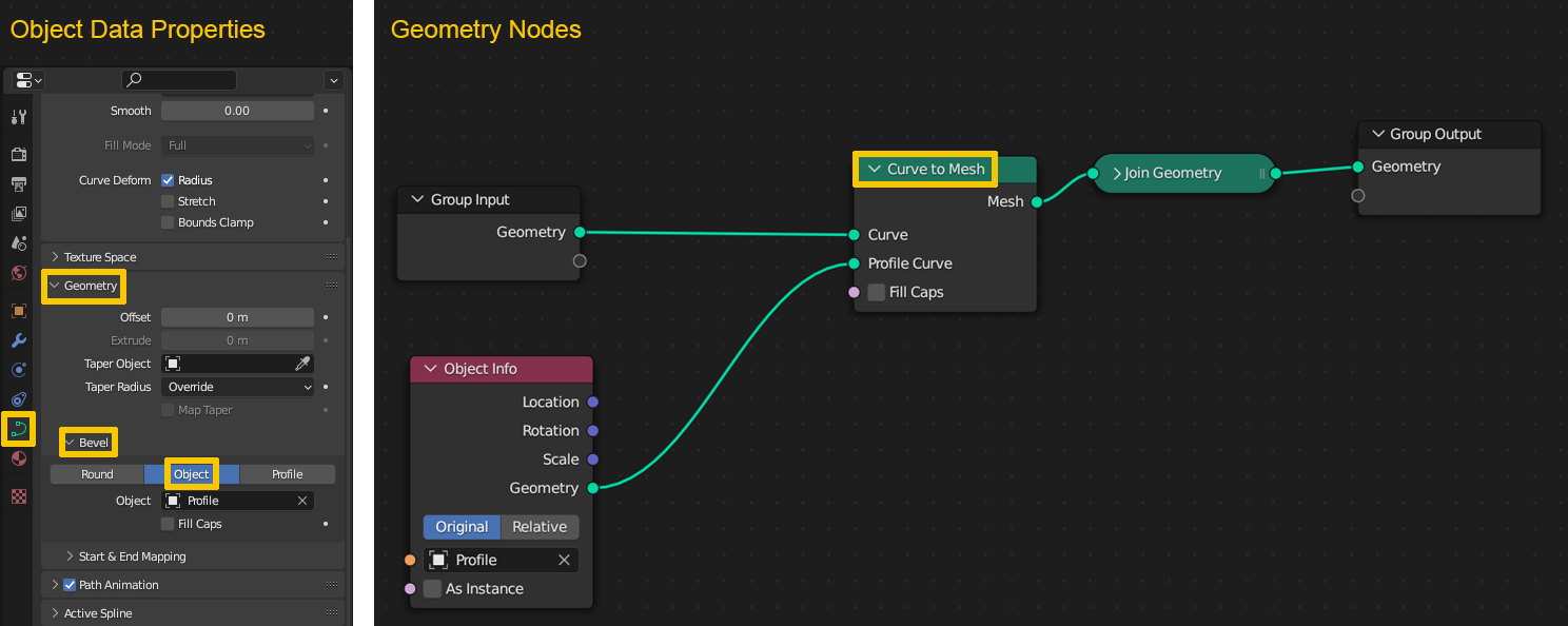
First of all a quick information: the alignment of profile curves along a curve path in Blender is different between the Geometry > Bevel > Object option in the curve's Object Data Properties and the Geometry Nodes method where you use the Curve to Mesh node to extrude a profile along the curve.
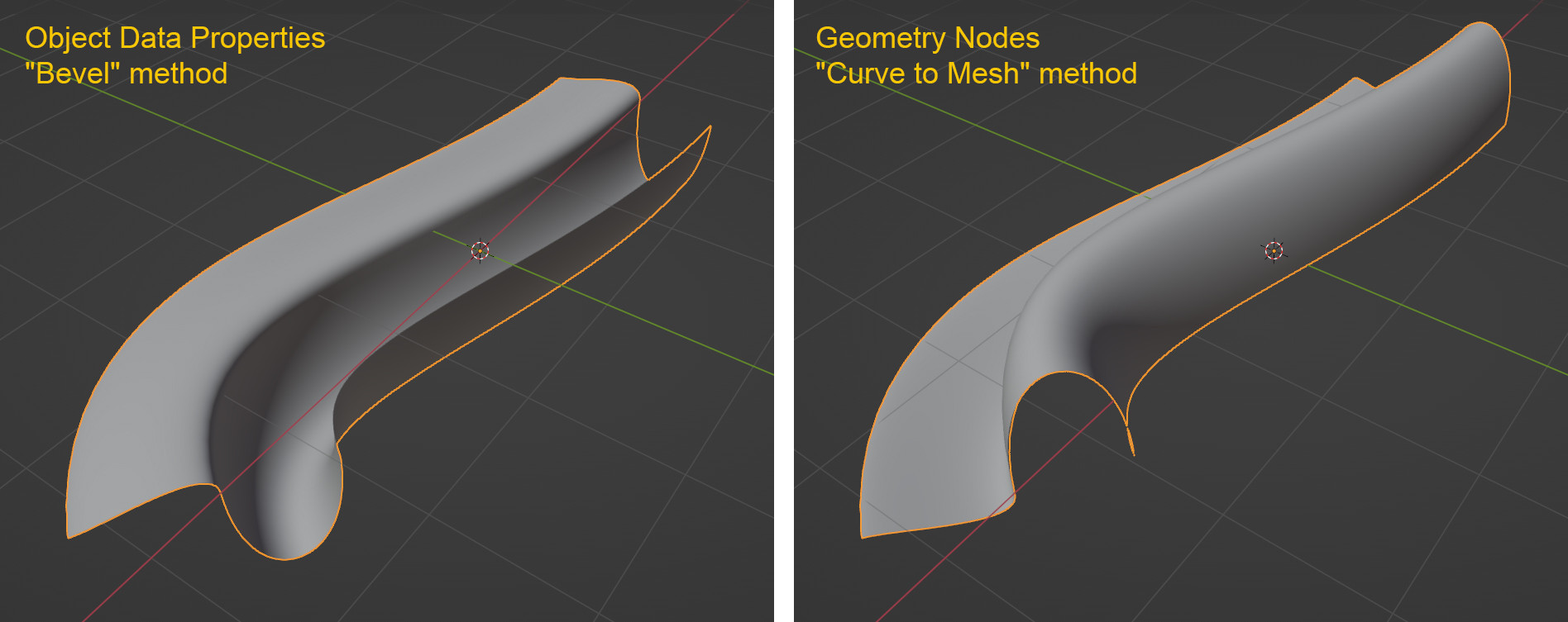
So these are the two methods, to the left the Object Data Properties where you can use a profile curve to "bevel" the curve to get a mesh. To the right a simple Geometry Nodes setup with which you can create a mesh from a curve and a profile. (I start with a curve instead of converting a mesh beforehand like in the question to use the same curve for both methods.)
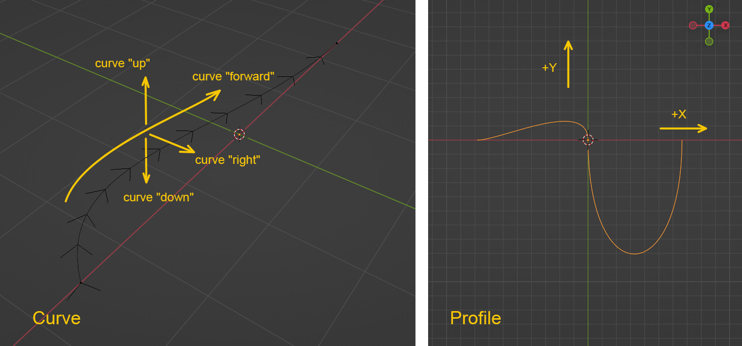
The next image shows the curve and the profile I used. Important: the following explanations are based on all objects having their rotations, scales etc. applied, otherwise you might get differing results.
On the left is the curve I used, a simple Bézier curve. In Edit Mode with Normals enabled you can see in which direction the curve is moving "forward". I also defined a "right" side of the curve as well as "up" and "down" for convenience and demonstration purposes. On the right is the 2D profile curve in top down view so that you can see its XY alignment.
A comparison between the "Bevel" method and the "Curve to Mesh" method now shows a significant difference in the results. Both methods extrude the profile with its origin point on the curve, but while the "Bevel" method uses the profile in forward direction as it appears when you look at it top down - the +X is on the "right" side of the curve and the +Y is "up" - the "Curve to Mesh" method flips the profile. +X is still on the "right" side, but +Y is now pointing "down".
Looking at the profile curve again, this is what you discover: the "Bevel" method (left) extrudes the profile more "intuitively" correct (or at least so it feels to me), as if looking down on it is looking in curve forward direction. The "Curve to Mesh" method (right) seems to be somehow incorrect, as it is not just rotated 180° when looking down on it, but flipped (mirrored) on the X axis:
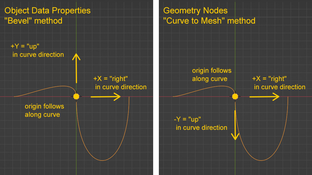
Admittedly I have no idea why the "Bevel" method works this way, because although it feels more correct to me, I will show why the "Curve to Mesh" method is more consistent with the curve's orientation and since you are especially interested in the Geometry Nodes version, let's focus on that.
To see what's going on with the curve I built an object with arrows pointing in the direction of the three positive axes X, Y and Z and instanced it on the curve. Without any aligned orientation, they simply still point to global X, Y and Z.
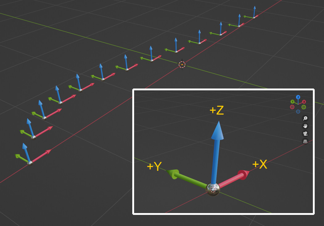
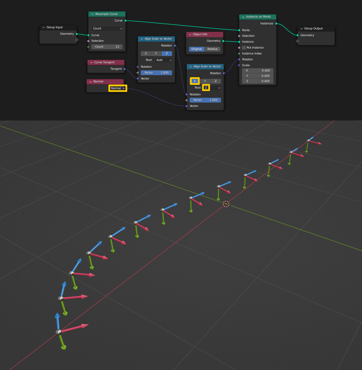
Let's find some alignment for the arrow object. Since our profile lies in the XY plane, we assume the Z direction as the curve's "forward" direction. Forward is in this case the curve's tangent. So I use an Align Euler to Vector node to align the object's Z to the tangent vector. Now the blue Z arrow is pointing "forward", the other arrows are not aligned yet:
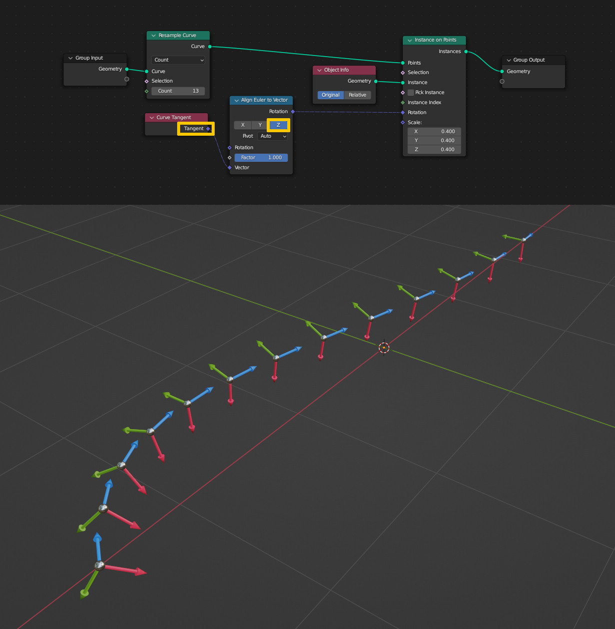
Both methods have +X pointing to the "right", which is the direction of the curve normal. In order to align the X of the object with the normal, the output of the Align Euler to Vector needs to be plugged into another Align Euler to Vector node. This time to align X with the already aligned Z axis as pivot. And if you look at the result you might notice the following: the +Y arrow is now pointing down. This is the "natural" alignment of the curve, this is the way the profile is oriented and this is why I called the "Curve to Mesh" method more correct than the "Bevel" method:
Although I defined the convention to use the terms "right", "up" and "down" on the curve, these directions are not always so easy to determine. In the previous example "right" was always in the XY plane and "up" and "down" were in Z direction. However, if curve points are tilted, this is no longer true. In the following setup I use the Set Curve Tilt node together with the Index to increase the tilt from start to end:
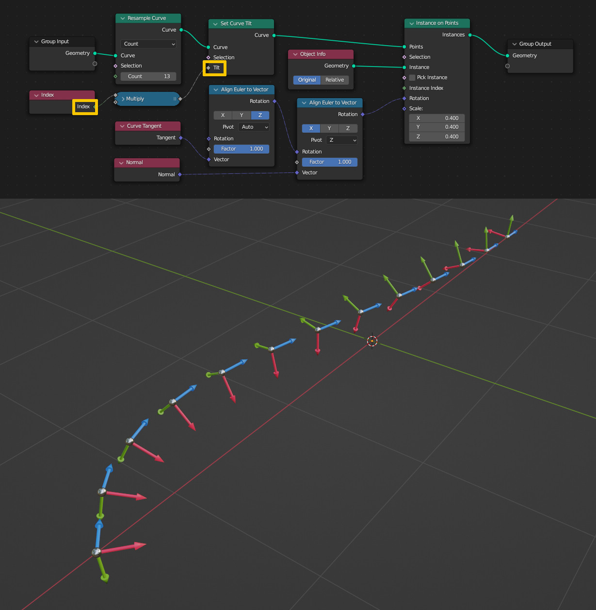
And of course this influences the alignment of the profile as well:
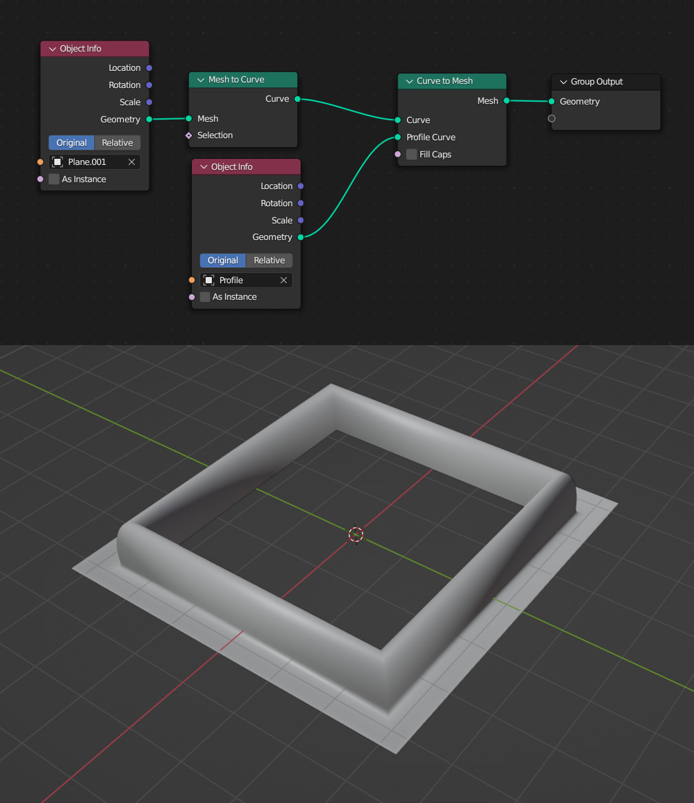
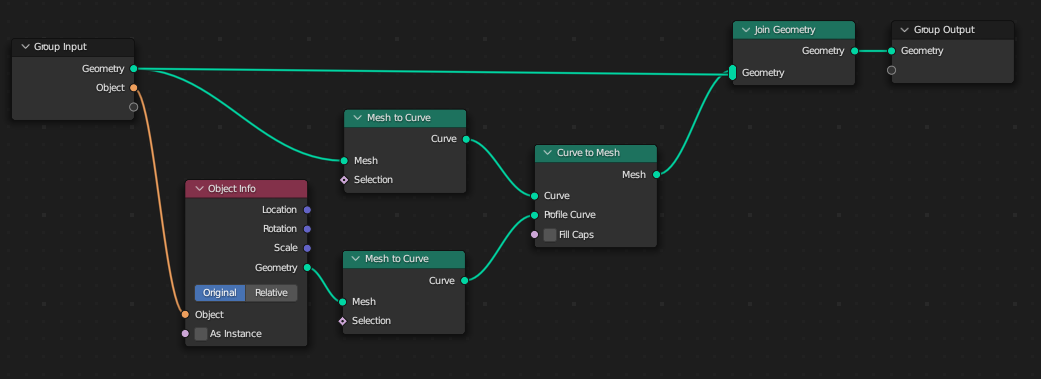
The "forward" on the other hand is clearly defined: in Geometry Nodes, it's the direction from the point with the lowest index to the point with the highest index. On a curve object in Edit Mode this direction is shown (like before) with the Normals overlay enabled. In your case where you have a mesh plane as original object, this option is not available. Nevertheless the direction is the same: from lowest index to highest index.
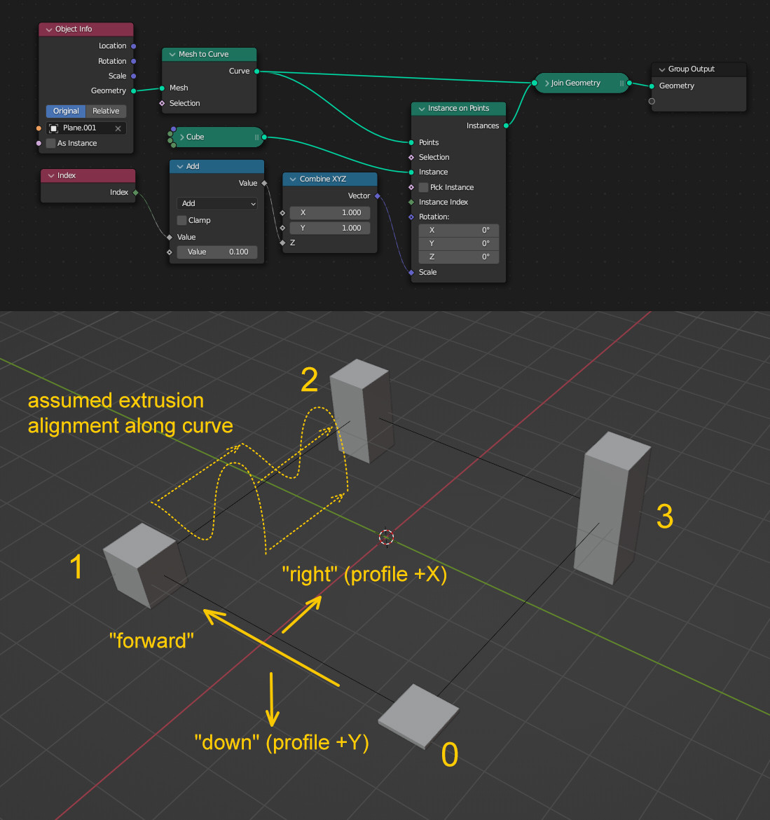
In the image below there is a mesh plane converted to a curve. To simply show in which order the points are numbered I instanced cubes on the points and scaled them on the Z axis by their index, i.e. the smallest cube is index 0, the largest index 3.
With the things said before this means the "forward" direction of the curve is going from 0 to 1, then further to 2 and 3, the curve's "right" side (which is the profile's +X) is pointing inside the square and the curve's "down" (and profile's +Y) is pointing down Z. From this the assumption can be drawn that the profile will be extruded along the curve as shown by the dotted lines:
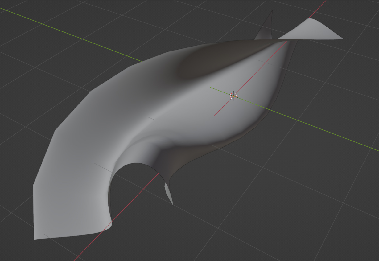
Using a Curve to Mesh node now with the profile plugged in, the result is as expected. The "bulged" part is on the inside of the square pointing upwards:
