Apologies for the title, this question is somewhat difficult to ask.
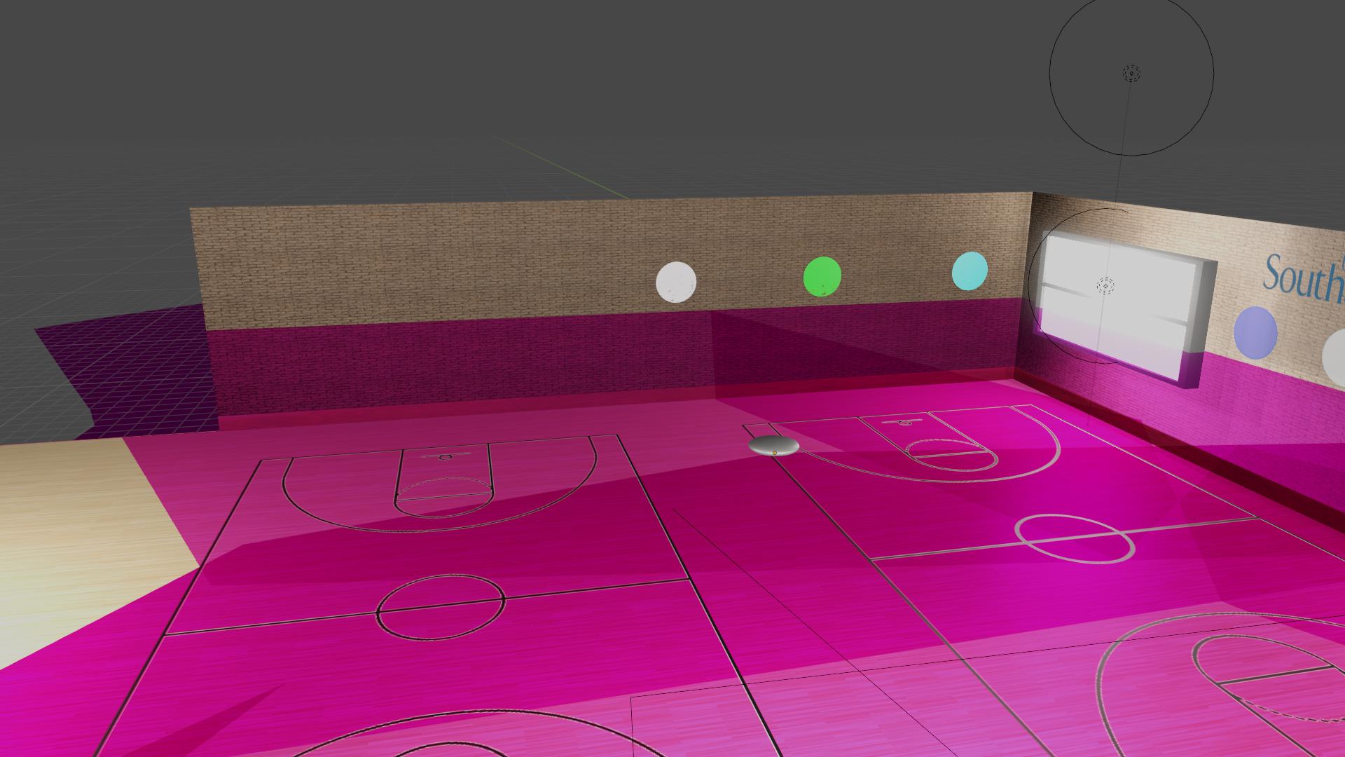
I am currently trying to create a 3D render of a blimp for a project. The aim of the project, without Covid, would have been to implement computer vision systems on the blimp so that it can autonomously navigate an indoor space. As this is now impossible, as part of our hand-ins, we need to make a video showing what it "could" do. As part of the video I am trying to show the field of vision of the cameras mounted on our blimp. Imported from Solidworks is a shape that represents the camera's FOV. I have parented this to the blimp so that it follows its movements. I have currently made this object transparent by reducing the alpha value in an attempt to demonstrate where the cameras can see, i.e. the giant pink mess in the pictures.
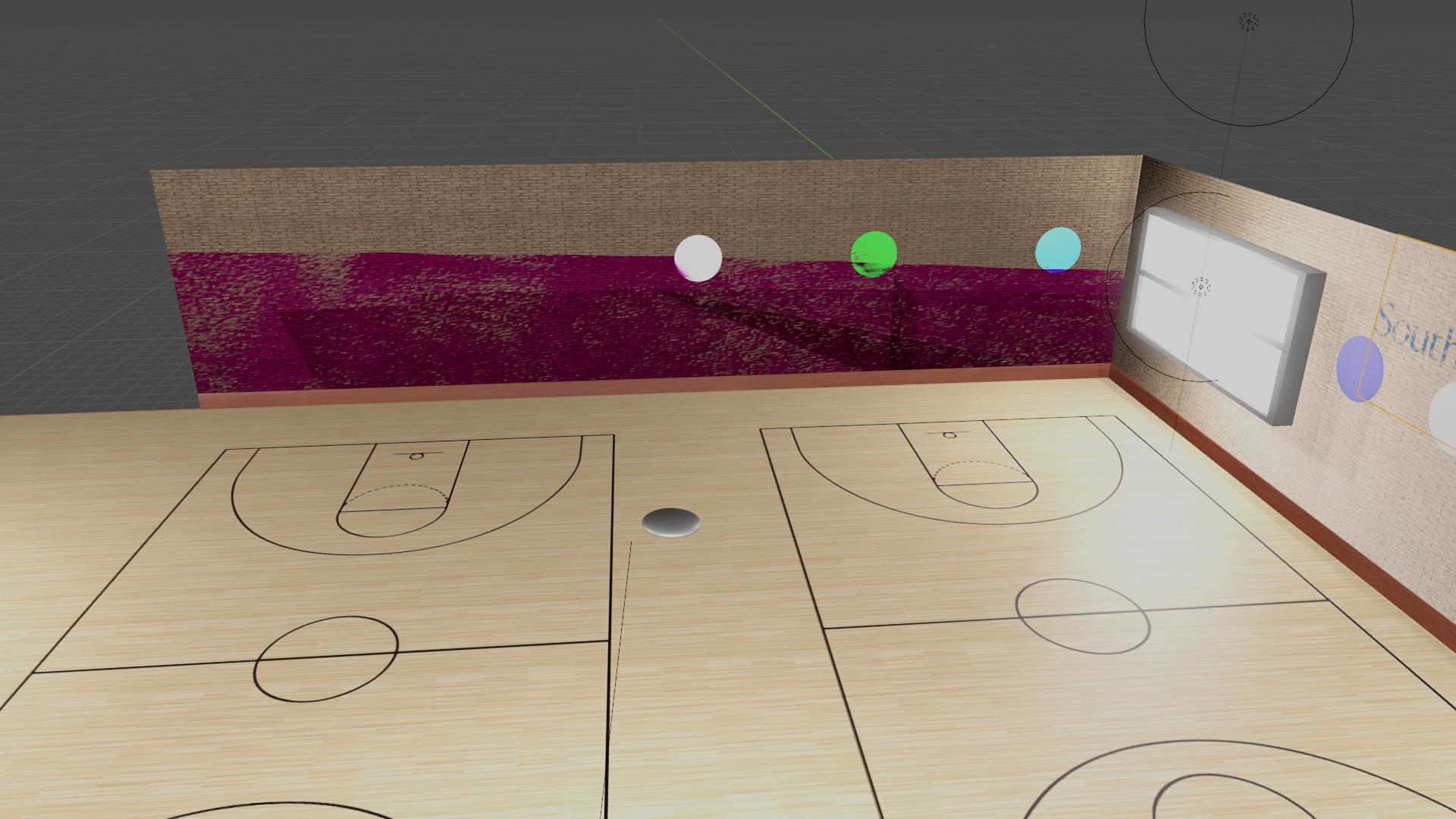
My goal is to make it so that this object is only visible on the walls/floor, where it intersects. This would be a better of the camera FOV, it would allow for more intuitive understanding of where on the walls/floor it could see. This is important, as the camera needs to be able to see a certain amount of beacons on the wall for the computer vision to work.
Things I have already attempted:
I have tried using a shrink-wrap modifier to wrap the shape to the surfaces. This does not have the desired affect as it distorts the shape.
I have also tried using a Boolean intercept with the required surfaces. This made a horrible mess.
Any help is greatly appreciated, the images attached show what I currently have and what I'm trying to get:
 This is what I currently have, a big translucent object that represents the cameras field of view.
 This is the affect I'm trying to achieve, except on all walls and the floor, I made this using shrinkwrap, but as said it distorts the object.


