3
$\begingroup$

Part with Engraving in Mesh

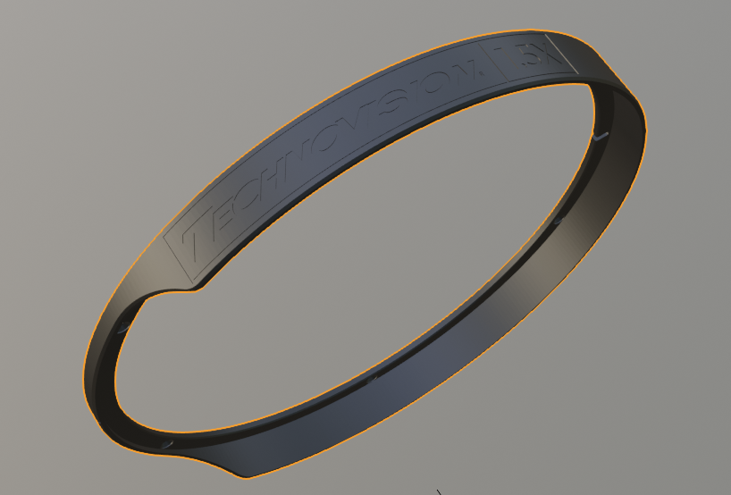
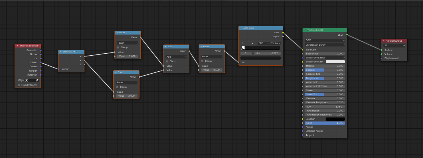
So I am currently working on a CAD rendering and decided to give Blender a try instead of Keyshot. One part is a black ring with engraved writing (silver/white) on it (in the mesh since it is a stl import). I thought just like color by z hight it should be possible to assign color by radius -> lower parts of the ring white and higher parts black. So my approach was calculating the radius and input into a color ramp set to constant.

First attempt

Also tried to add a Mapping Node to scale the vector etc. but no luck with that. I am quite new to blender so I guess my understanding of the texture coordinate object vector might be wrong. Switching the xyz outputs didn't help either.

Maybe someone could help me out here.

$\endgroup$
2
  • 5
    $\begingroup$ Your node setup seems correct assuming your object coordinates are correctly aligned and orthogonal in relation to the ring plane $\endgroup$ Commented Mar 31, 2020 at 15:05
  • $\begingroup$ Make sure the transforms of your ring are at scale 1,1,1. You can do it by hitting CTRL + A, and choosing 'Scale' $\endgroup$
    – Gorgious
    Commented Mar 31, 2020 at 17:03

3 Answers 3

4
$\begingroup$

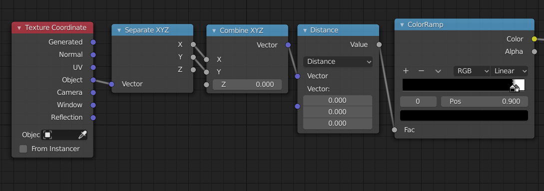
Your node setup looks correct, although it could be made slightly less verbose by making use of the Vector Math: distance node.

enter image description here

I've managed to make it work on a torus. Perhaps you should try:

  1. Making sure the origin is in the centre of the ring.
  2. Tweaking the ColourRamp slider's Pos values so that the results of the previous node operations fall in their vicinity. As of right now, yours are set to 0 and 0.077, it seems; for me the spot was around 0.9 .
$\endgroup$
4
$\begingroup$

As @Duarte has commented, your set-up should work.. things to bear in mind:

  • Blender's Object space is measured in Blender Units, from the object's origin, and in the orientation of its local axes.
  • The Color Ramp node maps a 0-1 'Fac' range, your radii might be outside that altogether.
  • You would need three stops on the Color Ramp; the area you want to pick out is between 2 others in radius, and it looks as if it would be very fiddly to hit the right spots

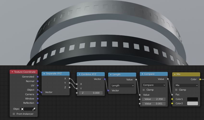
To get this example, I created a temporary single vertex at the center of the ring, and used the Measure tool to find the distance from it to the shallow relief. The nodes then compare the XY radius of the shading point to that length, with enough tolerance to catch all of the inset faces, also bearing in mind, under the hood, the faces are flat: the radius is not constant.

enter image description here

$\endgroup$
2
  • $\begingroup$ I tried your setup and could not find the Compare Note... using 2.8.2 and it should be in math but no compare there. $\endgroup$
    – B G
    Commented Apr 1, 2020 at 19:00
  • $\begingroup$ @BG it's one of the functions in the Math node $\endgroup$
    – Robin Betts
    Commented Apr 1, 2020 at 19:42
3
$\begingroup$

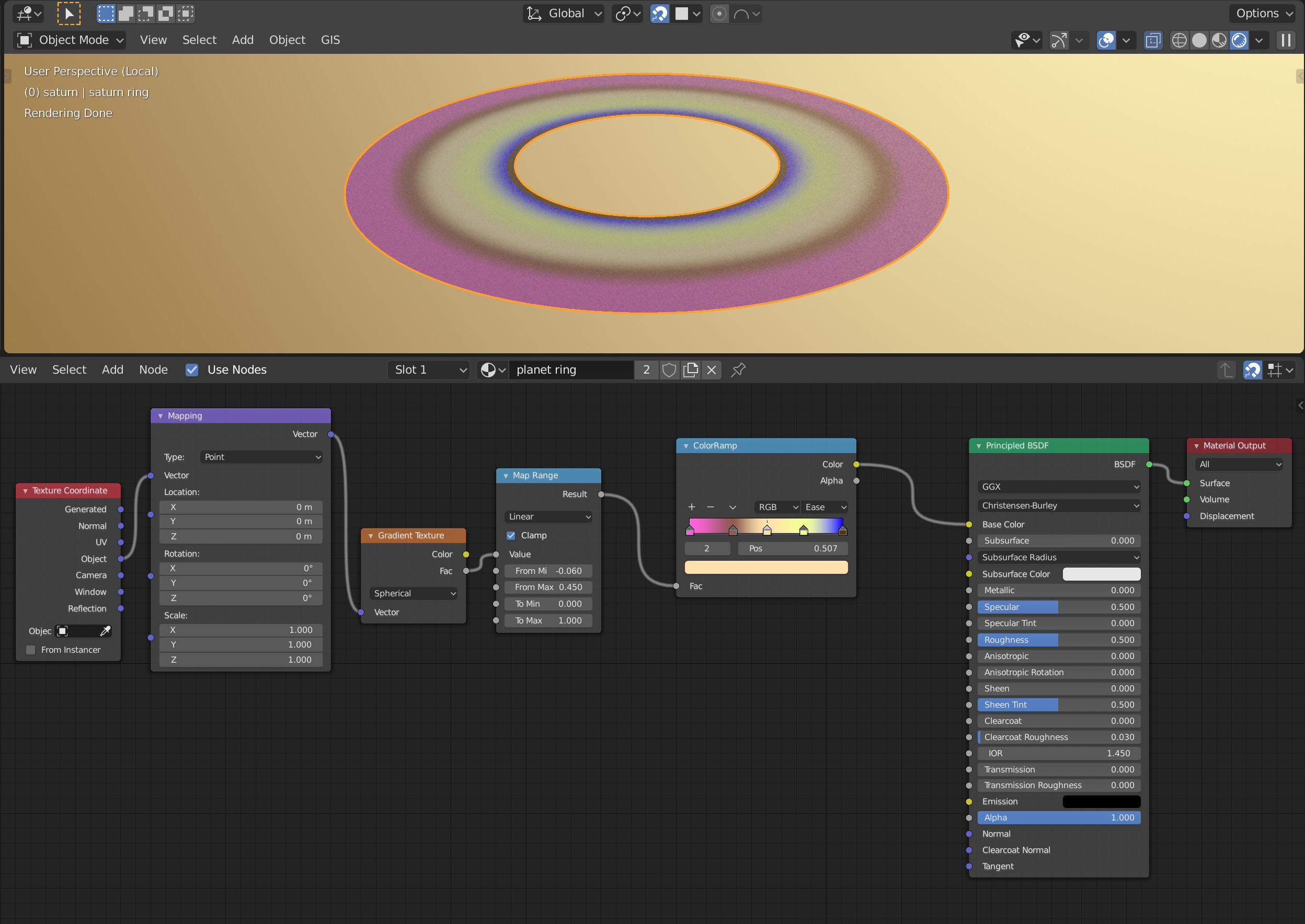
The material for the planet rings below (ignore the planet itself) changes the color based on distance from object center using object texture coordinate, Gradient/Spherical node and a map range to control the distance range to use. Change to Constant interpolation in the color ramp in order to have hard stops between colors.

enter image description here

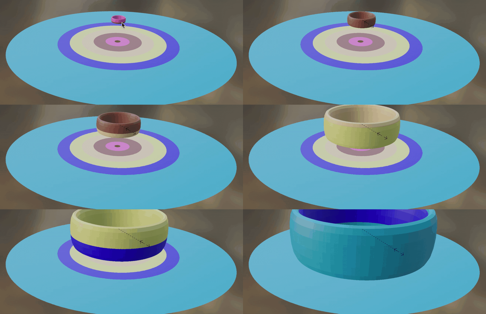
Change scale of your Ring in Edit mode in order to see the color changing based on scale (or Apply Scale to the object)

enter image description here

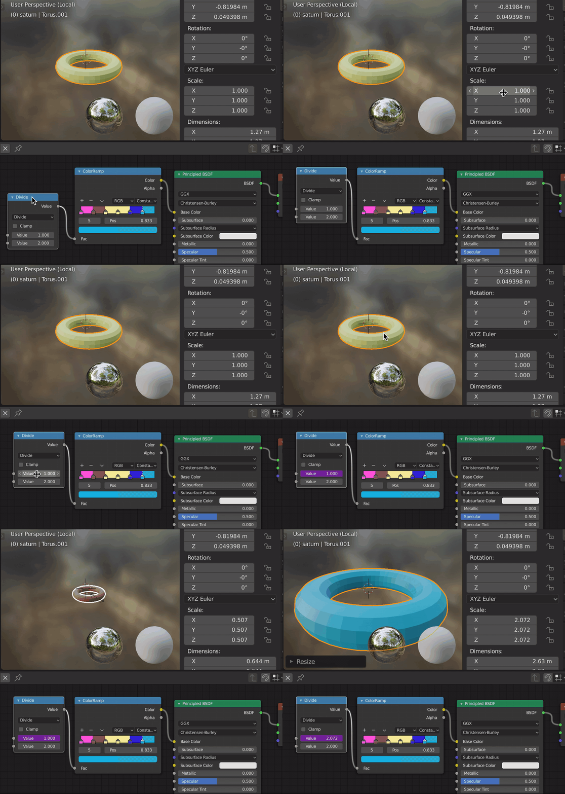
Another option is to use a driver for that same color ramp using the scale of the object:

enter image description here

$\endgroup$

You must log in to answer this question.

Not the answer you're looking for? Browse other questions tagged .