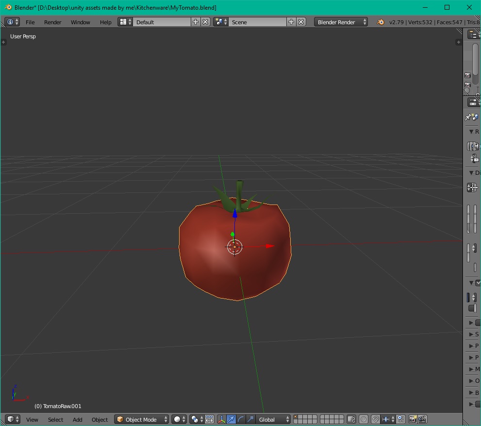
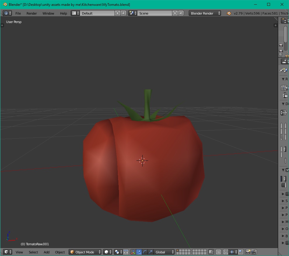
This is the result of mismatch in normals orientation.
Smooth shading averages normals of the vertices which compose the faces. On the surface where each face is connected to the neighbour face this will work as they share vertices and hence normals have the same orientation.
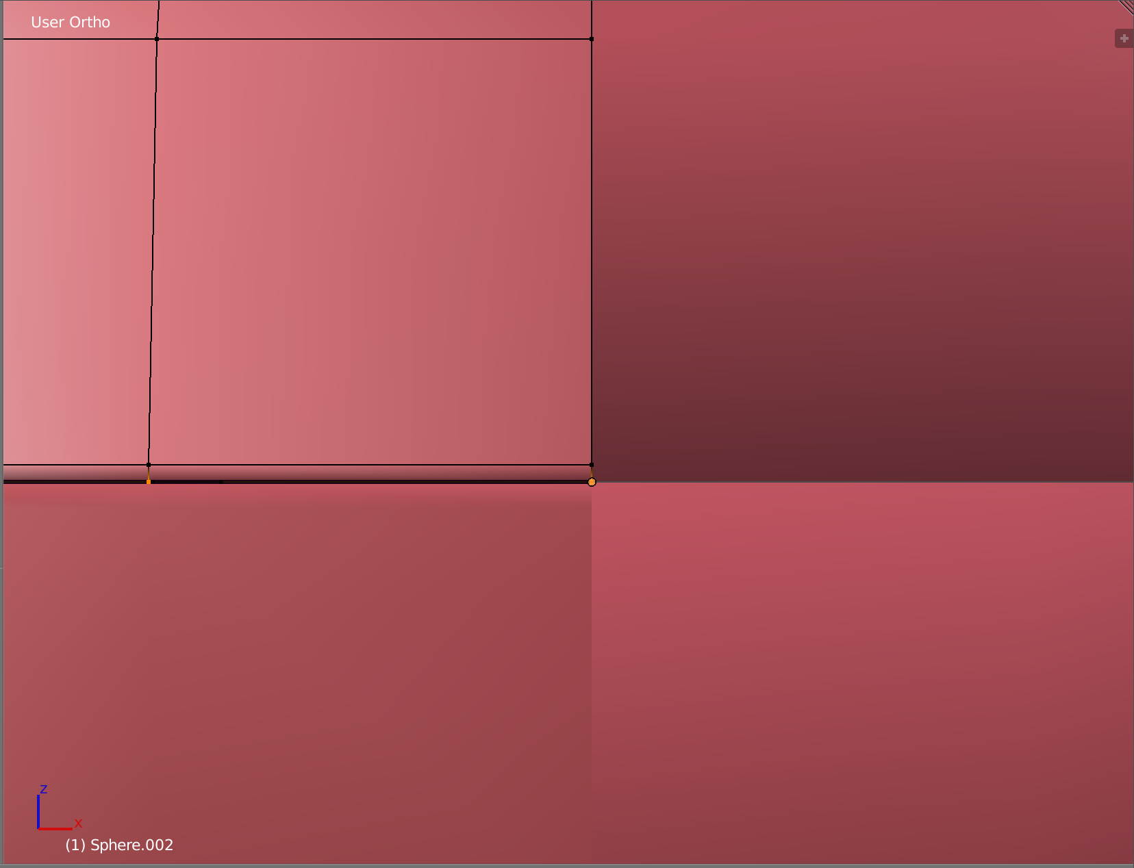
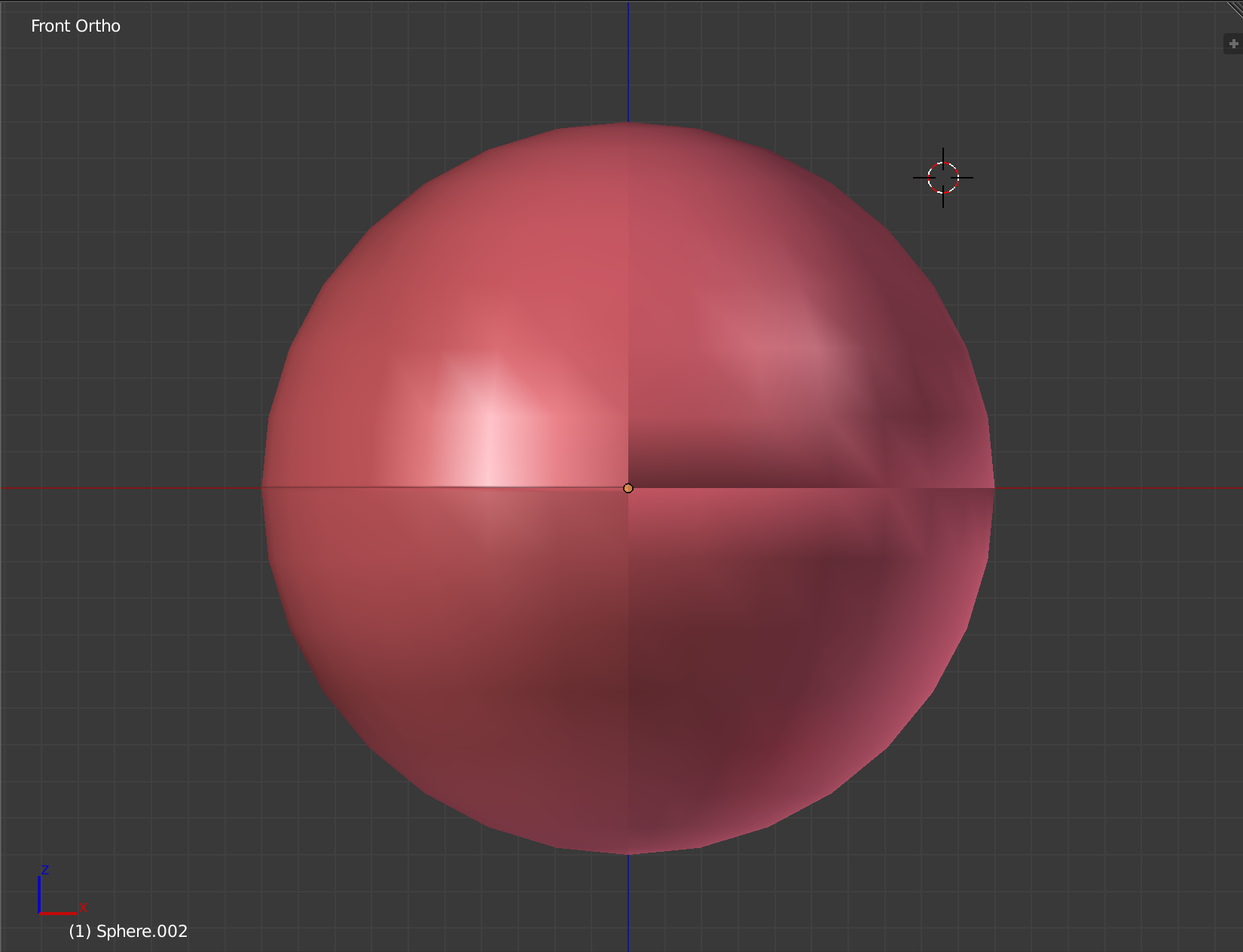
On the other hand when surface ends the normal of the vertex which is on the boundary loop won't be the same as above because it won't have neighbours to have the same average result of the normal vector orientation. Here's an example of a sphere with a segment cut out and left as part of the same object:
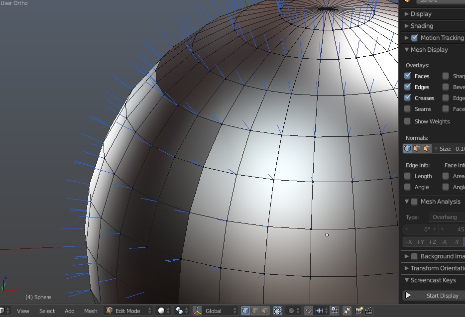
Blue lines show vertices normals' orientation. They are doubled and mismatch a bit where double vertices meet. And shading has visible artifacts there.
Often you will be advised to remove doubles to workaround that. If you need these as different meshes the easiest way is to split meshes into different objects in order to use modifier to transfer normals from one object to another, this is Data Transfer modifier.
After seperating segment into another object enter Edit mode, select boundary loop edge (Ctrl + E > Select Boundary Loop) and add it to a vertex group.
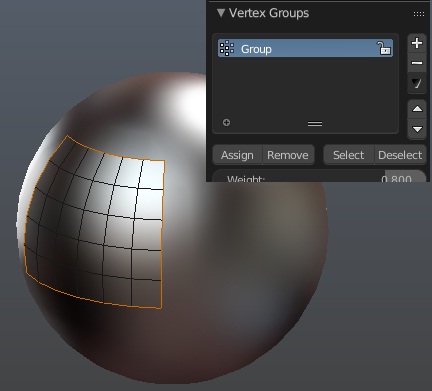
So that if you enter Weight Paint mode you will see red in the corners (weights of 1):
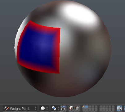
Do the same for the sphere itself:
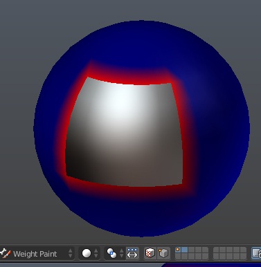
Then add Data Transfer modifiers for both objects. Choose Sphere as source object for the segment and Sphere-segment for the Sphere object in its settings. Enable Face Corner Data checkbox to tell modifier what to transfer. Choose Custom Normals below. In the Vertex Group field choose groups created above. Set Mix Mode for the modifier on the sphere to Add, leave default Replace for the one on the segment. Enable AutoSmooth in the Object Data tab to make both modifiers work.
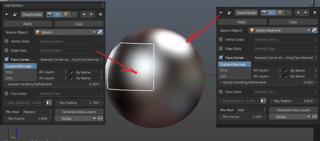
Now the cut out segment won't be seen as separate mesh.


