0
$\begingroup$

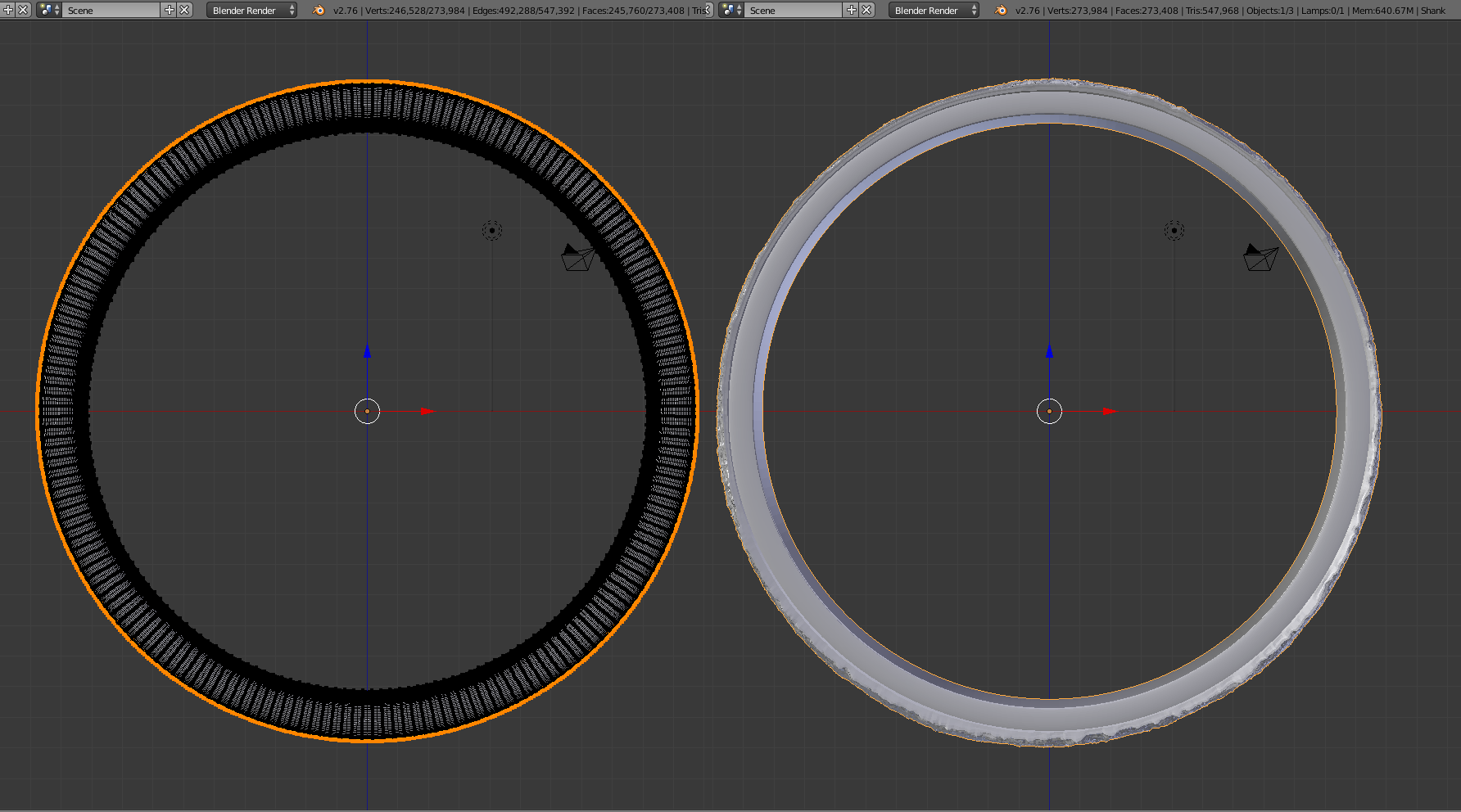
So I'm modeling a ring for myself, and I'm using a moon surface texture as a displacement map using a UV unwrap of just the outside of the mesh. But the displacement modifier seems to be afftecting parts of the mesh I don't want. You can see below that the internal diameter increases.

enter image description here

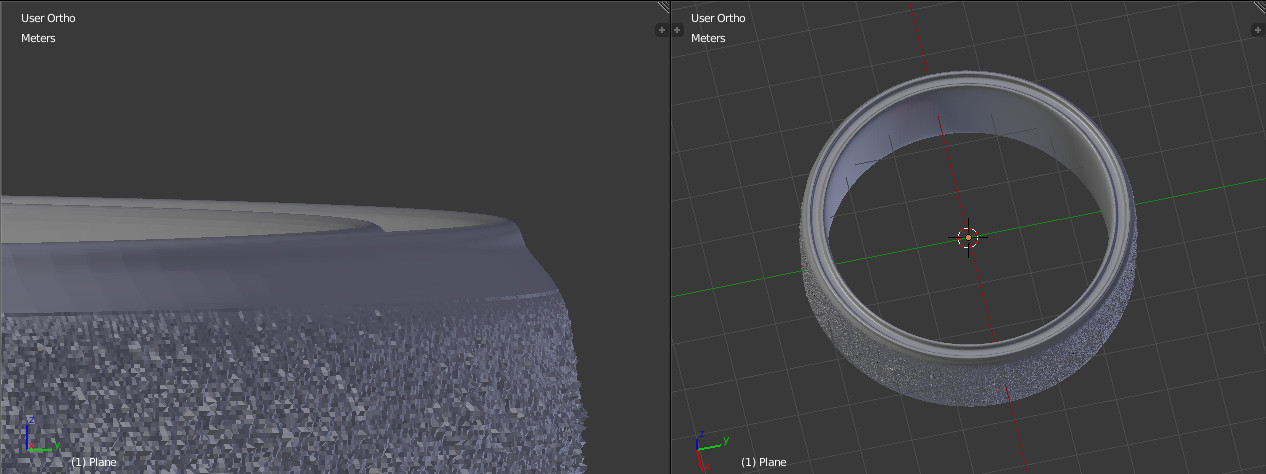
And I don't want this as obviously it will chance the ring size and it won't fit. Also I'm wanting the displacement to only affext the surface and for it to stay flush with the top of the ring but it has these sides that I want to get rid of.

enter image description here

Any help or tips will be greatly appreciated!

$\endgroup$
10
  • $\begingroup$ Displacement modifier has a 'vertex group' option which allows to displace only the vertices affected to this group. $\endgroup$
    – lemon
    Commented Mar 7, 2017 at 8:18
  • $\begingroup$ Thanks for that Lemon! I'm trying to get rid of the raised edge circled below. I tried editing the actual texture, put a black faded edge, but for some reason I still get the raised section. Maybe sculpting is the easiest way? [1]: i.sstatic.net/dCAN2.jpg $\endgroup$
    – MaxGoode
    Commented Mar 7, 2017 at 13:34
  • $\begingroup$ If I understand you well... simply remove the sides from the vertex group... or I don't get the point? $\endgroup$
    – lemon
    Commented Mar 7, 2017 at 14:15
  • $\begingroup$ I haven't got the sides in the group, when I apply the displacement modifier, on the edge of the vertex group/UV map I get this big dip at the sides: [2]: i.sstatic.net/y9sVE.png I've tried editing the UV map with a black edge in varying shades, but I still get that dip on the edge of the displacement where I want it to smoothly join. [1]: i.sstatic.net/g8Hdh.png The only way I can think is to apply the modifier, select all the edges in the bottom of the dip and scale, but that would be a very tedious task. $\endgroup$
    – MaxGoode
    Commented Mar 8, 2017 at 8:30
  • $\begingroup$ Vertex groups is a way to assign a value to the vertices of the group. This per vertex value can be between 0 and 1. About that and concerning the displacement modifier, the displacement will be max when the value is 1, intermediate when the value is 0.5 and there will be no displacement when 0. So simply use the vertex paint to lower the displacement on the border (you can make it smooth to 0 to the borders) $\endgroup$
    – lemon
    Commented Mar 8, 2017 at 8:49

1 Answer 1

1
$\begingroup$

A way to obtain a smooth transition from a displaced surface to the non displaced parts is to use a vertex group and to assign the good value for the vertex weights:

enter image description here

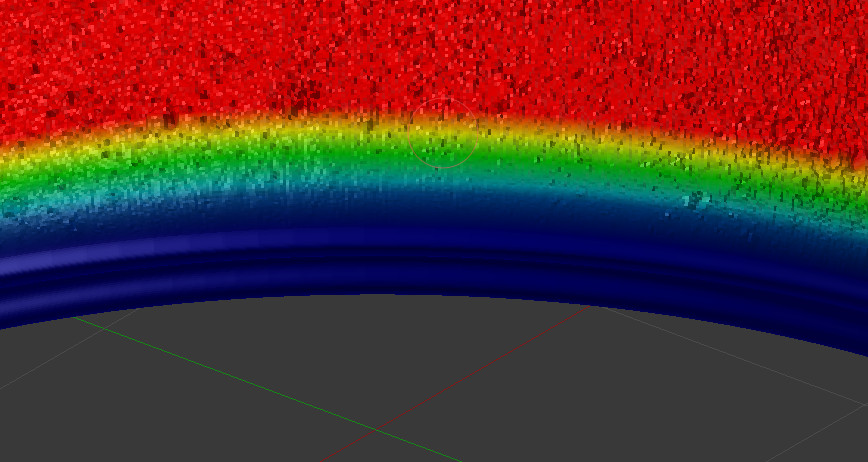
Here is a view of the weights (blue = the smallest value = 0, red = the highest value = 1):

enter image description here

This is done with the following steps (some of them will depend on your actual mesh and the way the ring is modeled):

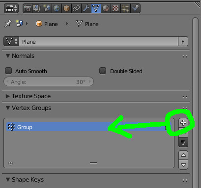
  • Create a vertex group: in the property panel, use the "plus" button as below

enter image description here

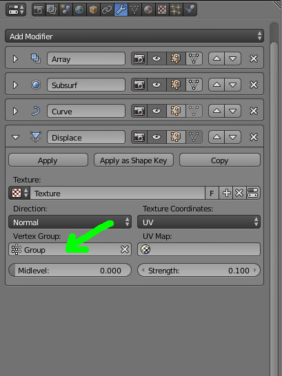
  • In the displacement modifier, assign the group:

enter image description here

  • Now we have to assign vertices to the group and fix their weights

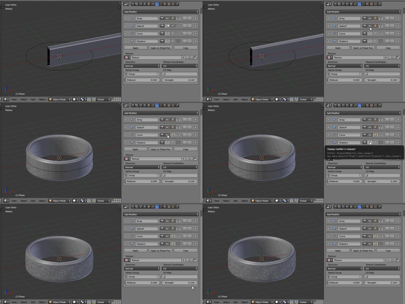
This part depend on how the model is done. Here I used a parallelepiped base, set an array on it, then subsurface and a curve:

enter image description here

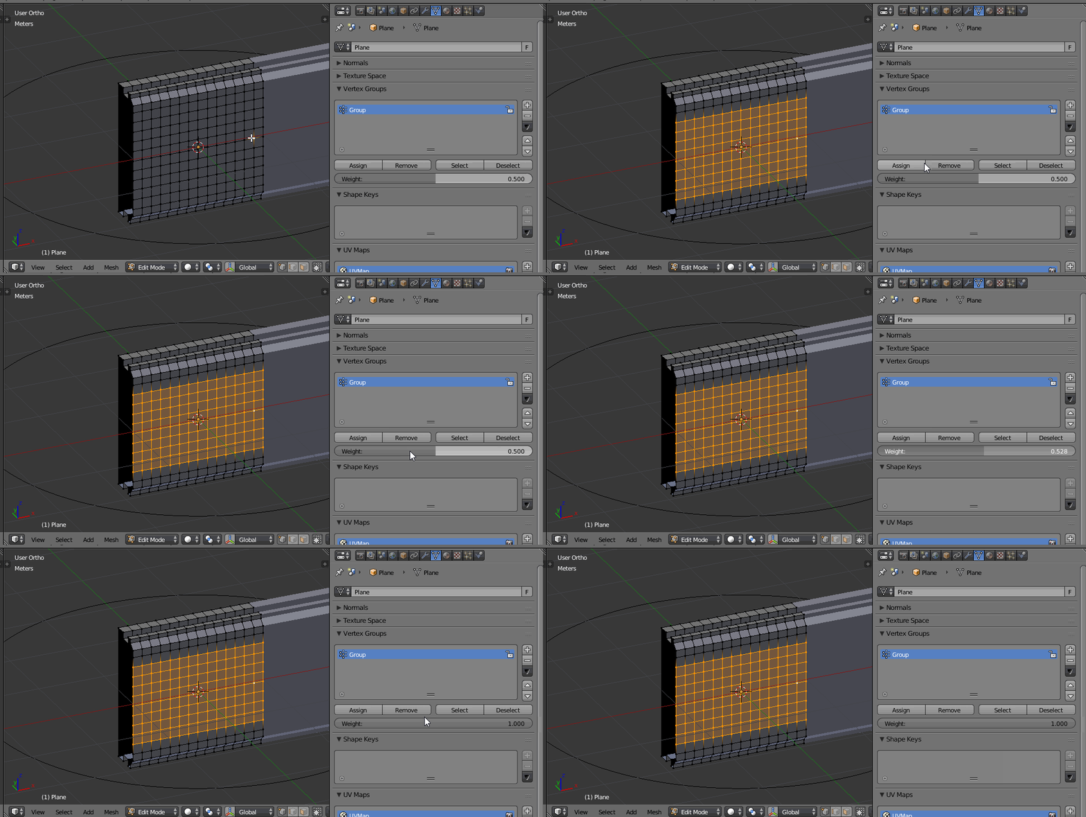
To assign the wanted vertices:

  • Select them
  • Tune the value of the weight
  • And assign

enter image description here

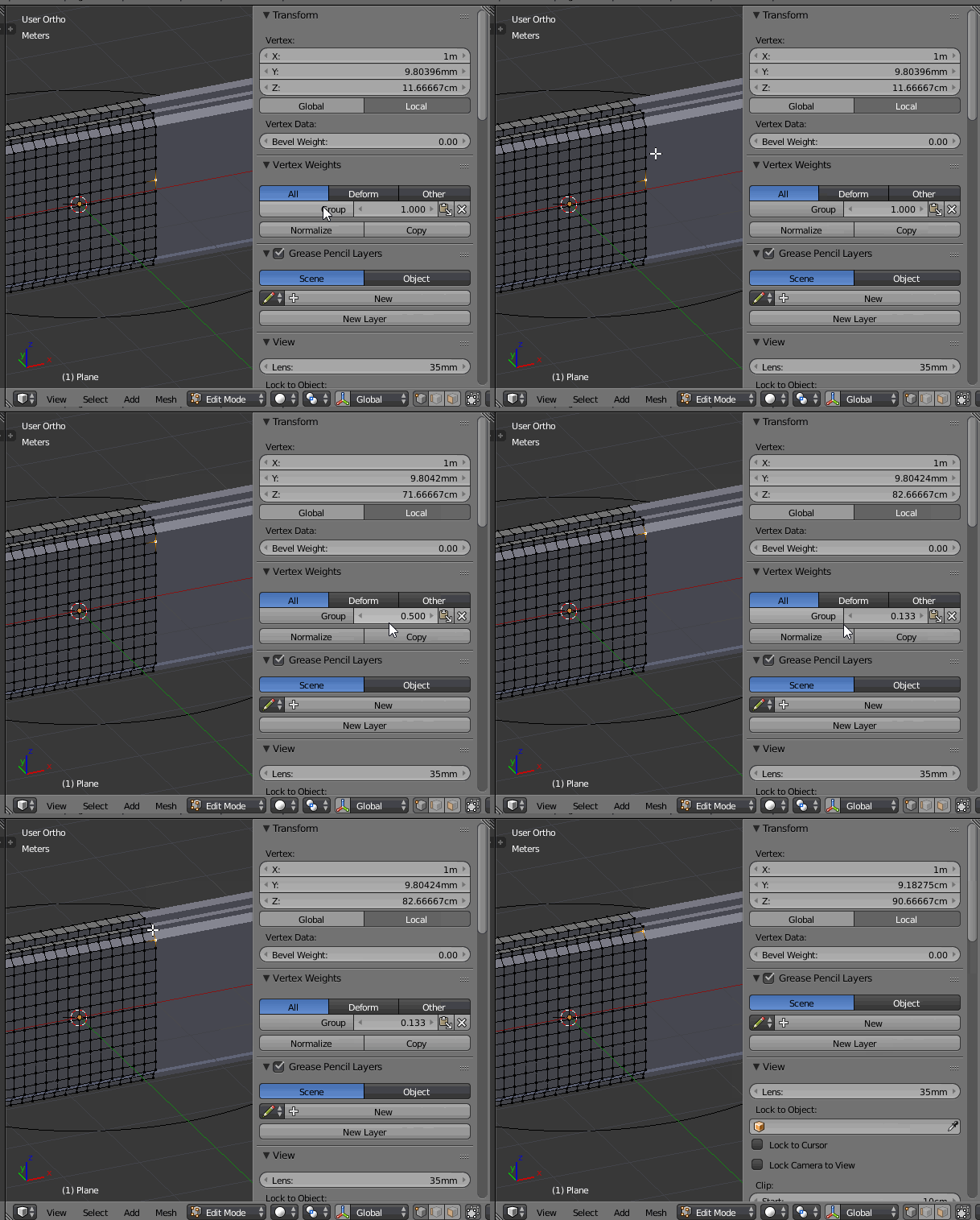
So going progressively to the border, while decreasing the weight value to 0, you obtain a smooth edge.

The values are visible vertex per vertex on the right side panel:

enter image description here

The blend file

$\endgroup$
1
  • $\begingroup$ Apologies for my late response, just back from holiday. Your response was perfect and helped me so much. Thank you very much $\endgroup$
    – MaxGoode
    Commented Mar 30, 2017 at 18:03

You must log in to answer this question.

Not the answer you're looking for? Browse other questions tagged .