(Using Blender 4.2.1)
Setup and resources
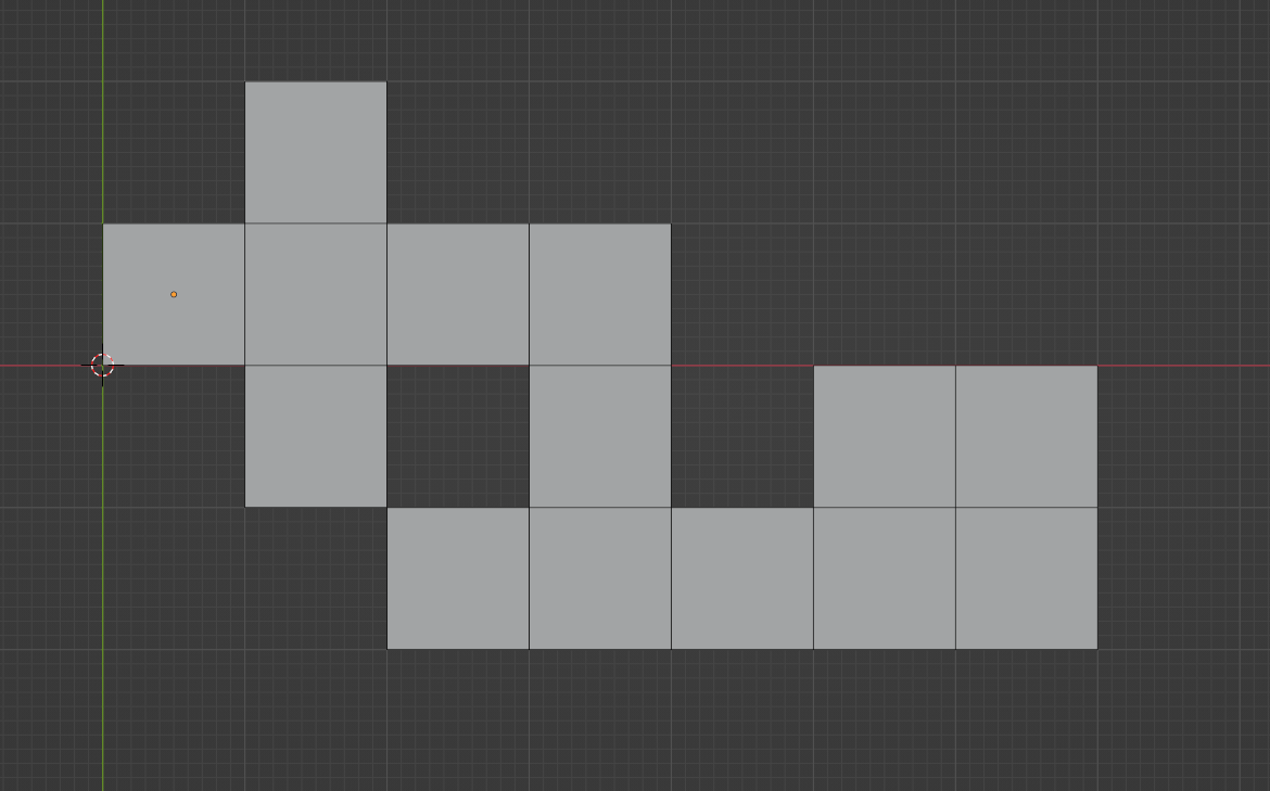
The GeometryNodes modifier is added to a Grid of 1x1 faces, some of them deleted in Edit Mode. This object origin is set at the center of a face to specify where is the "power source".
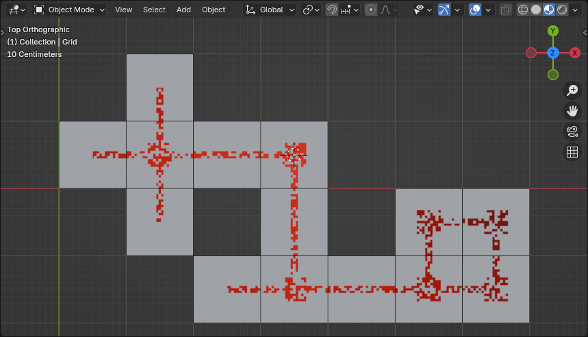

(Blender 4.2.1+)
GeometryNodes modifier
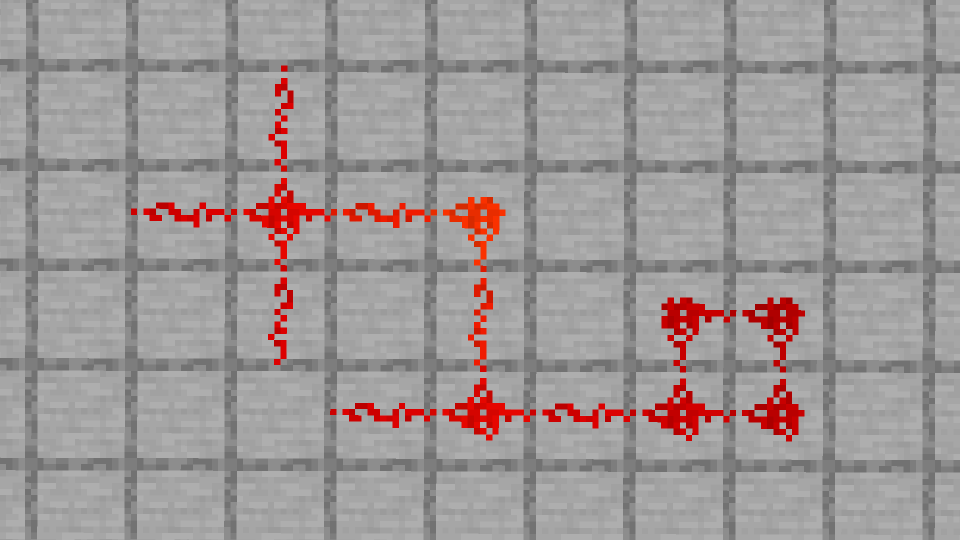
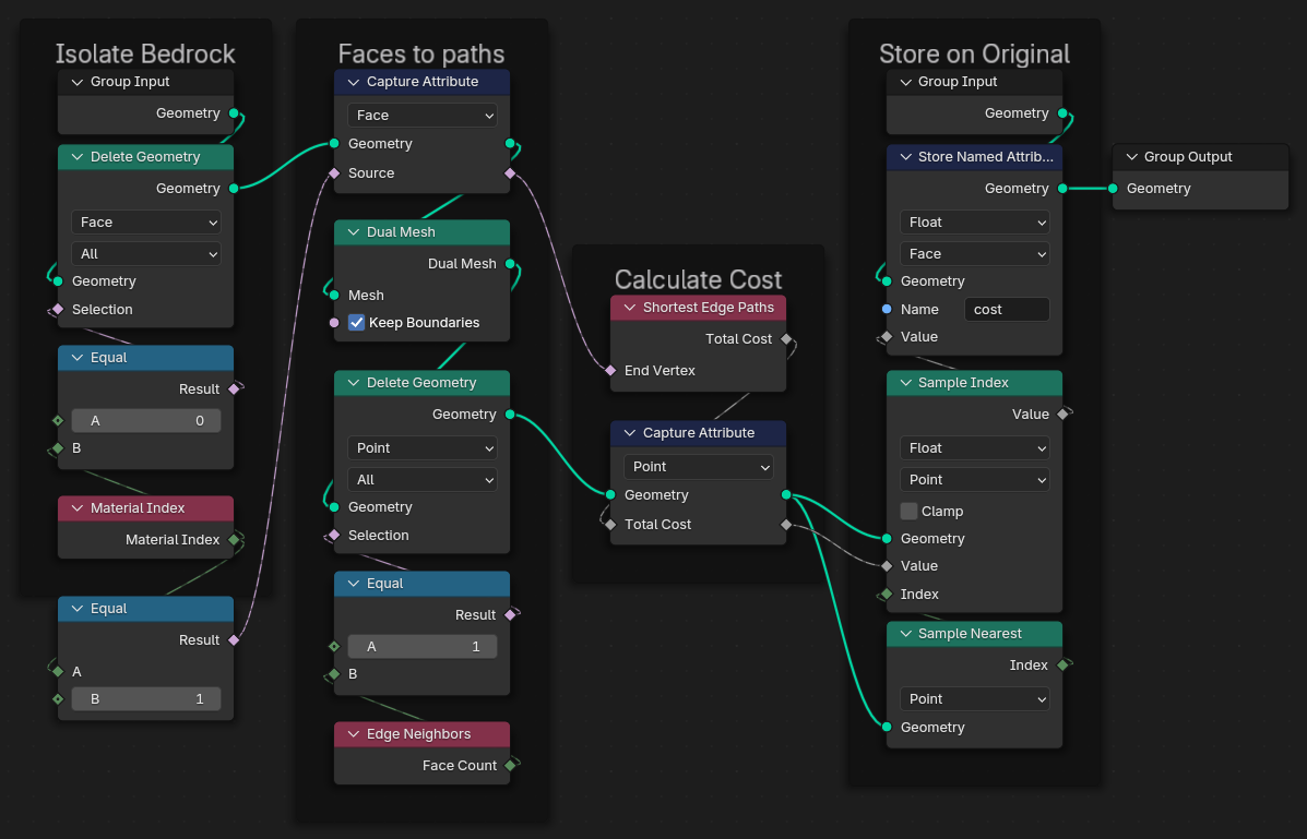
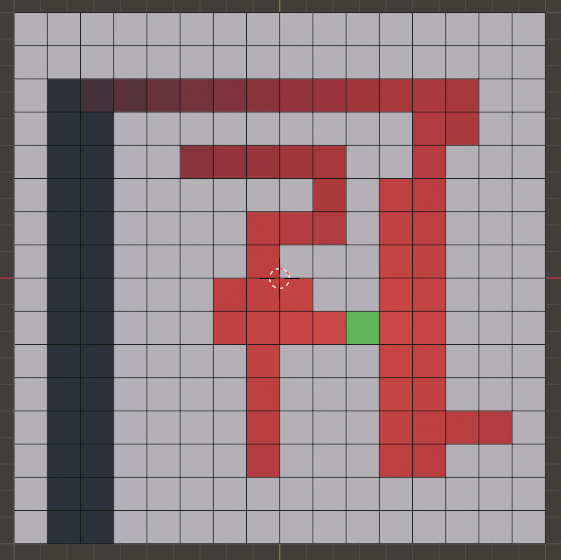
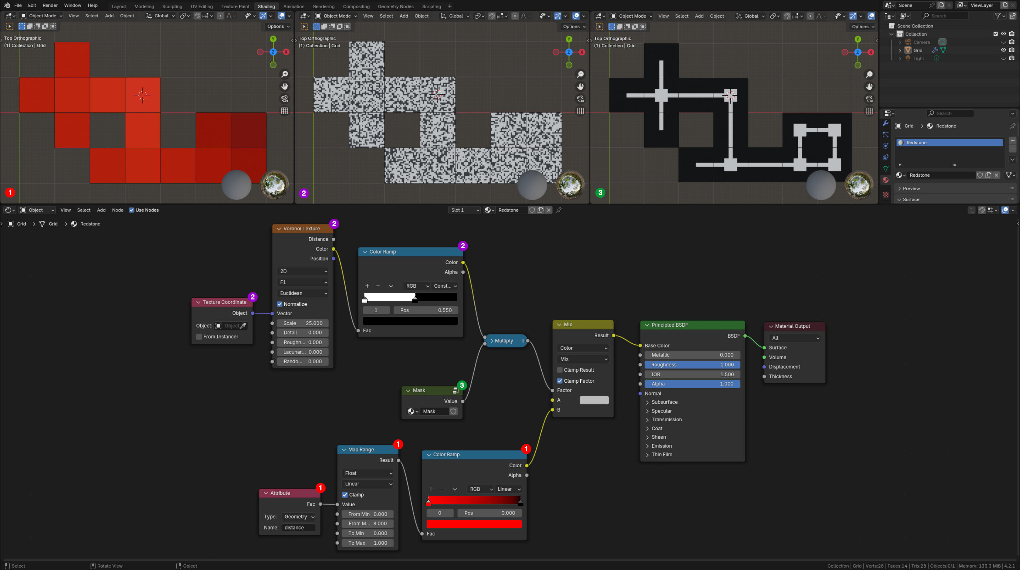
The GN graph is made of two Group nodes. The first one named "Distance" is building a collection of edges connecting the face centers along which is computed the shortest distance to the object origin. The second one named "Pattern" is encoding the direction of every edge connecting a face center to its neighbors. Both information are decoded in the Shader graph to control the color and the texture of the path.
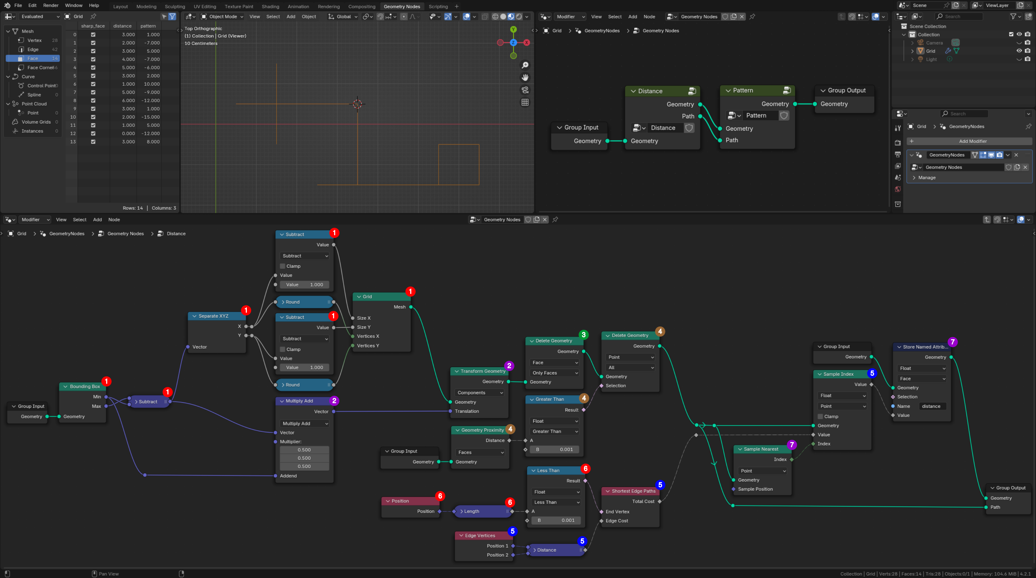
Path builder and distance computation
 1. A
1. A Grid is generated with one row and one column less than the input Geometry, whose dimensions are recovered by a Bounding Box node followed by a Subtract Math node.
2. This grid is initialized centered on the origin of the object carrying the modifier. So its vertices will be centered on each input face. But to do so, it must be shifted by half the diagonal of the bounding box relatively to its lower left corner (i.e. the output Min vector).
3. To build the path, only edges are required. So Faces are deleted.
4. Vertices that are not colocated with an input face are deleted also. The Selection mask for this operation is based on the Distance, between a grid Point and the Faces of the input geometry, computed by a Geometry Proximity node. This Distance is 0 (or very close to 0) for colocated vertices. The resulting mesh is displayed in the 3D Viewport.
5. The computation of the length of the shortest path between a vertex and the object origin is triggered by a Sample Index node set in Point domain. The length of every traveled edge is accumulated by a Shortest Edge Paths node.
6. The vertex terminating all paths is colocated with the object origin, so the Length of its Position vector is 0 (or very close to 0).
7. The distance computed at step 5 is transferred from the path vertices to the input faces using a Store Named Attribute node set in Face domain, combined with a Sample Nearest node set in Point domain. The Sample Index node of step 5 is recovering this Value based on the path point Index returned by the Sample Nearest node.
Pattern builder
Up to 4 edges might connect a face center to its neighbors, along each cardinal direction (E, N, W, S). These directions are thereafter associated with the indices (0, 1, 2, 3). The pattern $p$ defined by these connecting edges is stored per face using a binary code. It is encoded as:
$$ p = d_0 \times 1 + d_1 \times 2 + d_2 \times 4 + d_3 \times 8 = \sum_{j=0}^3 d_j \times 2^j \label{eq_binary_code} \tag{1}$$
with $d_j$ the weight of direction $j$. $d_j$ equals 1 for a connection in direction $j$, 0 otherwise.
Faces with at least one 90° turn of the path are rendered in a distinctive way. Such a face is tagged with a negative value of $p$. To detect 90° turns, it is taken advantage of the Boolean Attribute Domain Interpolation rules. These state that the value at an edge is True (i.e. $\neq 0$) if and only if the value at both of its vertices is True. Let $j$ be the index of a "virtual" edge connecting the directions $j$ and $j+1$, and $e_j$ its weight. $e_j$ is thus calculated as $d_j \times d_{j+1}$. Let $c$ be the indicator of the face status defined as:
$$ c = \sum_{j=0}^3 e_j \label{eq_turn_indicator} \tag{2}$$
c is equal to 0 if and only if all $e_j$ are 0, i.e. $d_j=0$ or $d_{j+1}=0$ for $j=0,1,2,3$. Consequently if c is equal to 0 (i.e. False), the path is straight and $p$ is set positive ; otherwise it is set negative.
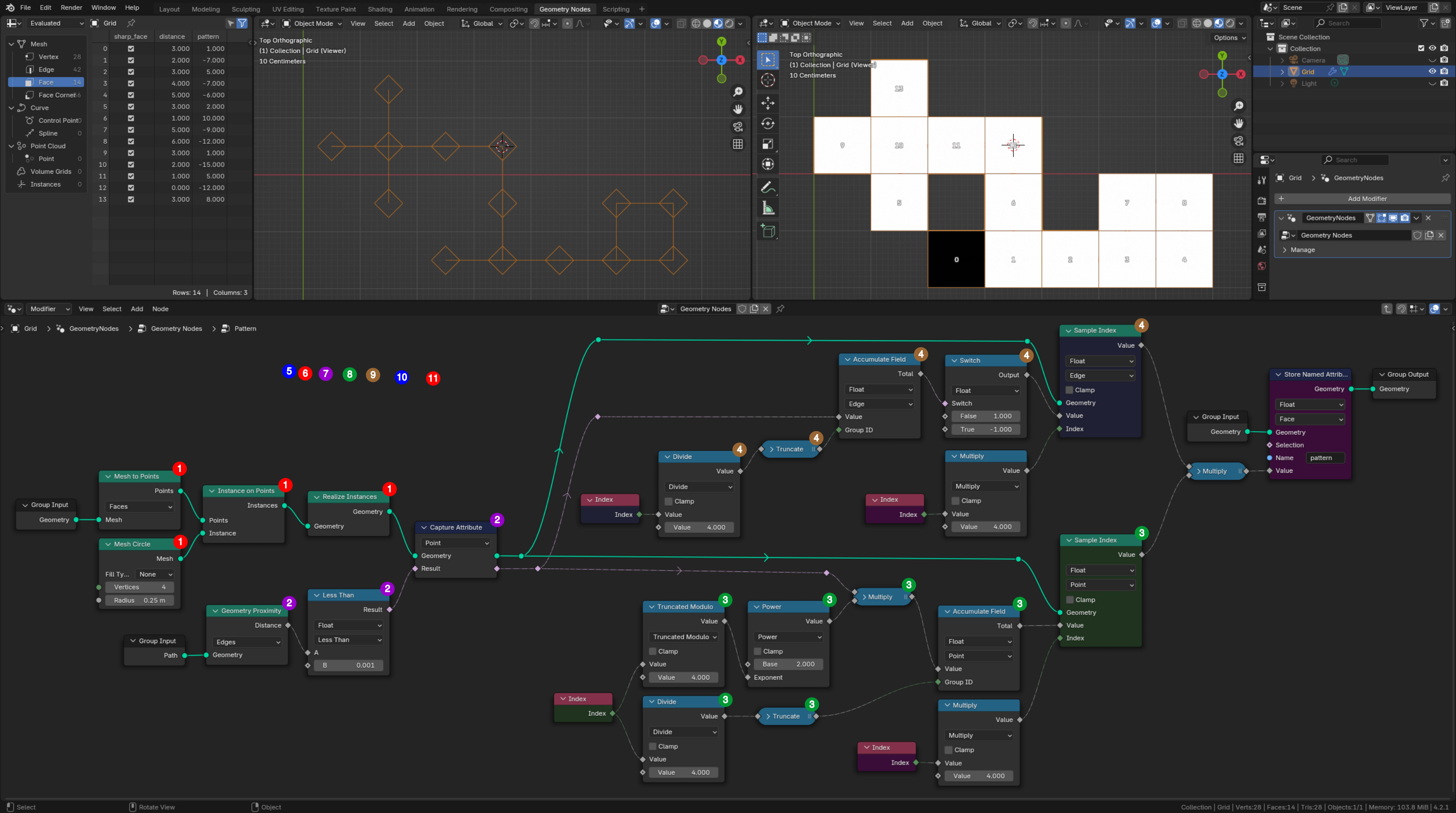
The top part of the following figure shows in the Spreadsheet Editor the achieved value of $p$ in the column labeled "pattern". The 3D Viewport next to it displays the faces index. (to be continued)
 1. To probe the edges connecting a face center, a
 Mesh Circle with 4 vertices is instanced centered on each input face. Its diameter is arbitrarily set to half the face size. It is to notice that these instances are made real to get the position of each point probe in the local coordinates system. The resulting connected probes are displayed in the 3D Viewport, superimposed with the path built previously.
2. The computation of the Distance between a point probe and an edge of the path is triggered by a Capture Attribute node set in Point domain. The distance is returned by a Geometry Proximity node set in Edge domain. The captured value is the weight $d_j$ stored as a Boolean. It is set to 1 for a probe next to an edge, and 0 for a probe away of all edges, using a Less Than Compare node.
3. The computation of the pattern $p$ is triggered by a Sample Index node set in Point domain. Let $n$ be the index of an input face. The indices $i$ of the 4 vertices spawned at step 1 on this face are in the range $4n$ to $4n+3$, i.e. $i=4n+j$ with $j=0,1,2,3$. Thus $j$ is computed as $i\mod{4}$, and $n$ as the integer part of $\frac{1}{4}i$. These values of $j$ and $n$ are used by an Accumulate Field node to compute the linear combination defined at Eq.(\ref{eq_binary_code}).
4.
(to be documented)
Shader
Main shader
 (to be documented)
Mask builder
 (to be documented)

