For a project with Godot, I need a path object, along which I can move a vehicle. Since I modeled the railroad track in Blender 3.3 using a Bézier Curve and a Curve Modifier, I converted the Bézier Curve to a Mesh and used a simple Python script (pseudo-code: see below) to export the Vertex Coordinates of my track generation curve into a json file.
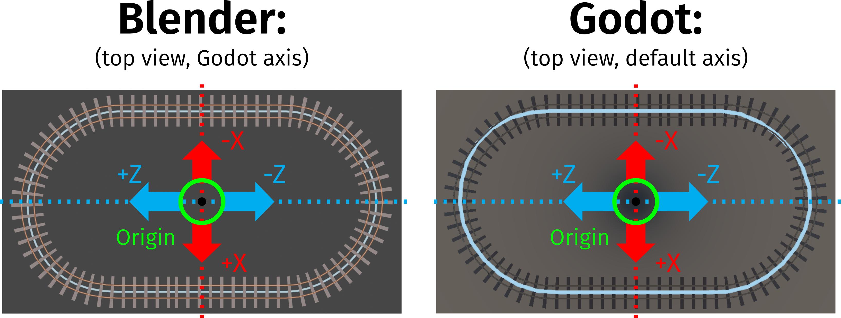
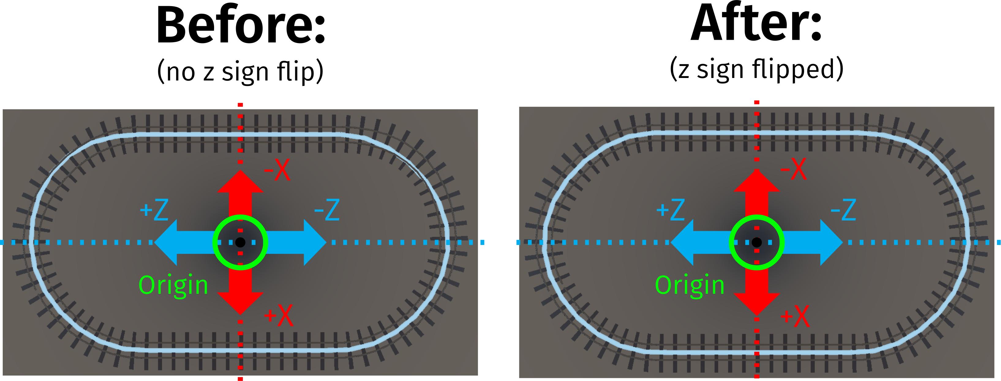
When importing the vertex coordinates into the Godot Path Object, a distortion in some of the rounded curve sections occur (see image below). The distortion is so bad that the Path is not usable for its intended purpose.
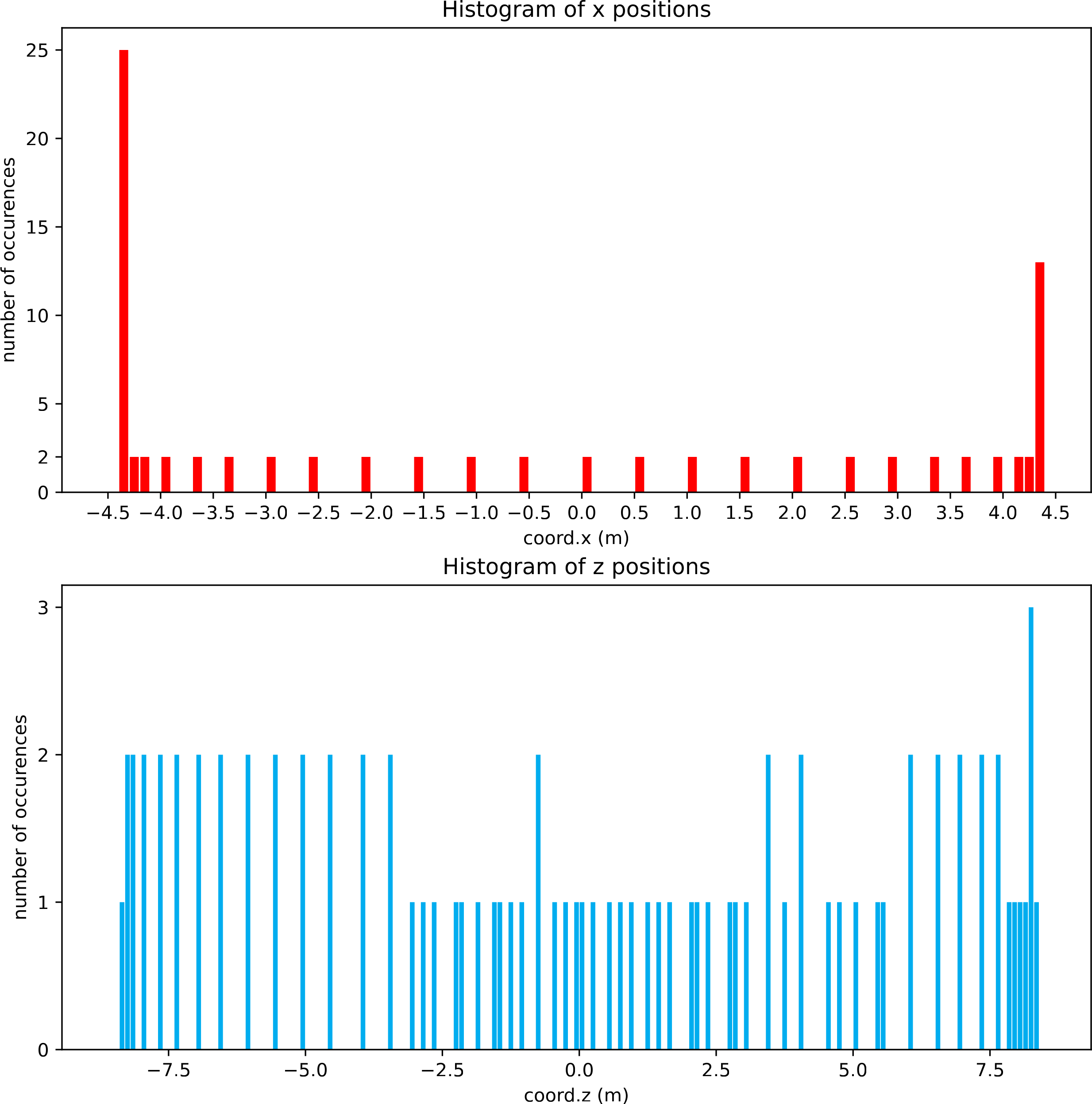
The image shows that the path in Godot shifts drastically out of the center position along the curved segments in the negative x coordinate regime, whereas in Blender the "same" path stays nicely centered everywhere. Since the mesh is completely symmetrical (placed all the points via coordinates) and has no modifiers applied to it (had issues previously with the mirror modifier destroying the vertex topology/ordering), this is strange. It is definitely not an issue with Godot (verified this very thoroughly). The asymmetry is present as soon as the data is acquired via Python within Blender (even before the export into the file). Plotting the histogram of the coordinates (plot below) shows a significant asymmetry along the x direction
(e. g. x = -4.3 m vs. x = 4.3 m) as well as the z direction (using the Godot convention here: y-up).
The asymmetry along the z direction is not as pronounced as its counter part, but cannot be attributed to histogram binning (bin size = 0.1 m) either.
Workflow
- Add Array Modifier to
sleeperandrailProfilemeshes. - Add Curve Modifier to
sleeperandrailProfilemeshes with following settings:Curve Object: trackCurve,Deform Axis: -Y(other settings do not work at all; however, this returns the desired output flipped, so step 7 and step 8 become necessary to flip it). - Select
sleepermesh,railProfilemesh as well as thetrackCurveBézier Curve and duplicate them withShift + D. - On the mesh duplicates, apply first the Array Modifiers, then the Curve Modifiers.
- Select the mesh duplicates and join them with
Ctrl + J. Rename the resulting mesh totrack. - Select the
trackCurveBézier Curve duplicate and convert it to a mesh viaObject Context Menu -> Convert to -> Mesh. Rename it totrackPath. - Select the
trackandtrackPathmeshes. Rotate them by 180° around the y axis viaR + y + 180to rectify the orientation issues induced by step 2. - With both meshes still selected, apply the rotation to prevent any issues with
Ctrl + AandApply -> Rotation. - Make sure that only the
trackPathmesh is selected and run the Python vertex coordinate export script.
The code (based upon the answer to this question) I use to write the json file is as follows:
import bpy, bmesh

###########################################################################################################
######## OBTAIN Vertex Coordinates ########################################################################
### source: https://blender.stackexchange.com/questions/1311/how-can-i-get-vertex-positions-from-a-mesh ###
###########################################################################################################
obj = bpy.context.active_object

if obj.mode == 'EDIT':
    # this works only in edit mode,
    bm = bmesh.from_edit_mesh(obj.data)
    verts = [vert.co for vert in bm.verts]

else:
    # this works only in object mode,
    verts = [vert.co for vert in obj.data.vertices]

# coordinates as tuples
plain_verts = [vert.to_tuple() for vert in verts]

###########################################################################################################
######## EXPORT Vertex Coordinates ########################################################################
###########################################################################################################
exportString = "{\n"
_pointCounter = 0
_iterationLength = len(plain_verts)-1

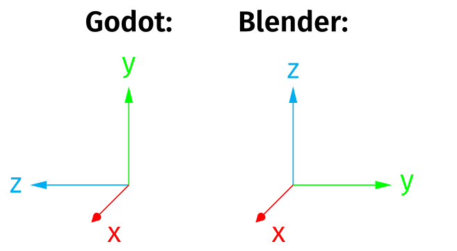
# formatting the data: x,y,z (Blender) -> x,0,y (Godot) + json specific syntax
# x = element[0], y = element[1], z = element[3]
# z != 0 to prevent any issues with float precision
# (Path Mesh is lying on xy plane in Blender, so z should be 0 in theory, but not in reality ...)
for element in plain_verts:
    exportString += "\t \"" + str(_pointCounter)+"\": [" + str(element[0])+", 0, " + str(element[1]) + "]"

    if _pointCounter < _iterationLength:
        _pointCounter += 1
        exportString += ","

    exportString += "\n"

exportString += "}"

# Exporting the file
exportFile = open("/Path/to/Export/file.json","w")
exportFile.write(exportString)
exportFile.close()
Important facts
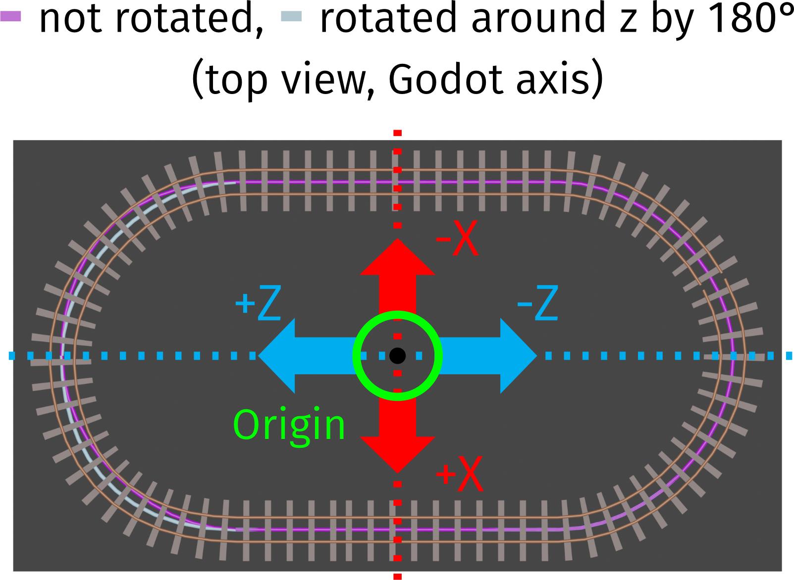
Rotating the trackPath in Step 8 is absolutely necessary. Otherwise, there is already in Blender a distortion along the positive z axis (Godot convention).
Questions:
- Can there be any influence of the camera/viewport on the result of the vertex coordinate calculation (like a mix-up with screen space coordinates)? I could not find any change in outcome whilst playing with the related parameters (neither in the resulting path in Godot nor in a file diff of the json files). Even though I think this is a very unlikely cause, I would like to ask this question, because I encountered many oddities in Blender over the years...
- Is this perhaps a rounding/float precision issue related to the bpy routine I am using?
- Is there a better way to access/export the vertex coordinates out of Blender? I only need points, no edges/faces. Some of the solutions suggested in this thread did throw an error in Blender 3.3... If possible, I would like to omit parsing complex export formats like stl/fbx/gtlf etc.

