1
$\begingroup$

I'm trying to model the following plate in blender: enter image description here
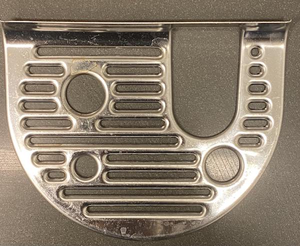
I tried bending a plane to form the general shape of the plate, and then adding solidify, boolean cutouts and then bevel them.

At this point, whatever I do goes sideways really fast - the bevels overshoot or don't appear at all, the cutouts don't end up round, etc.

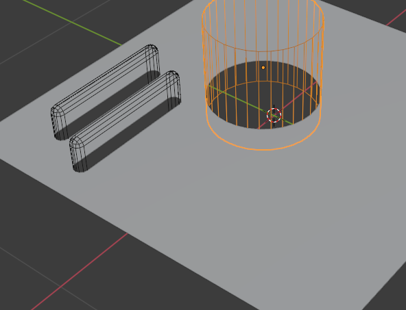
Here is an example of a simple attempt - I start off with a plane and a cutout (I have to bevel the cutter so that I have the round corners properly:

enter image description here

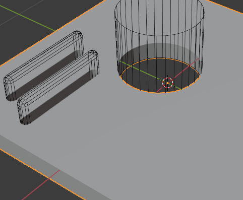
I then add solidify and bevel:

enter image description here

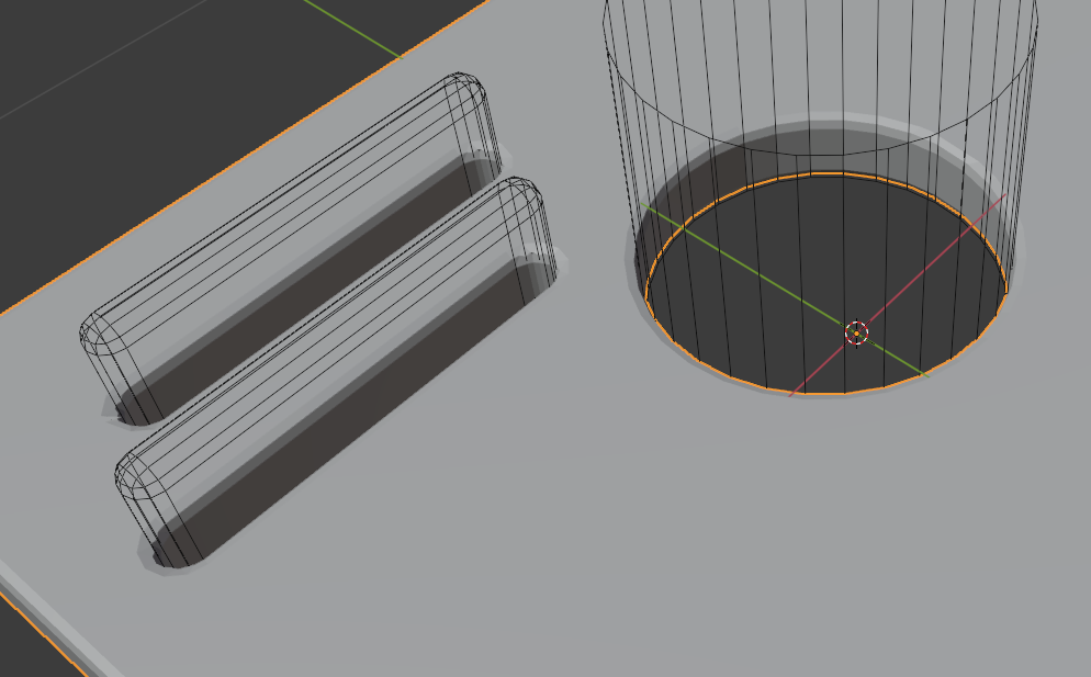
The bevel doesn't show, because clamp overlap is on... When I turn it off it either messes up the geometry, and the widest I can get it and still have it look reasonable is this:

enter image description here

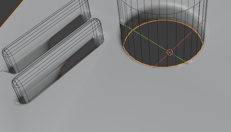
Adding subdivision before the boolean and/or bevel doesn't help much either:

enter image description here

Can someone direct me, or help me understand what I'm doing wrong? Is my entire approach to the process wrong? Am I using the modifiers in a wrong way?

Thanks in advance!

$\endgroup$
3
  • $\begingroup$ well, the easiest answer is: do all booleans and then fix your topology before you try to apply subdiv or bevel to it... if you cut into mesh like that you will create a lot of ngons, you will need to remove them $\endgroup$
    – MikoCG
    Commented Sep 27, 2021 at 12:07
  • $\begingroup$ I think the tool that cut those holes has a slight taper, which is why the top part of the round hole has a bigger radius than the bottom (inside) part. I might try tapering the cylinder to form the slope between the top and bottom and not using a bevel at all. $\endgroup$ Commented Sep 27, 2021 at 14:09
  • $\begingroup$ Possibly relevant: blender.stackexchange.com/questions/234450/… $\endgroup$ Commented Sep 27, 2021 at 17:48

1 Answer 1

3
$\begingroup$

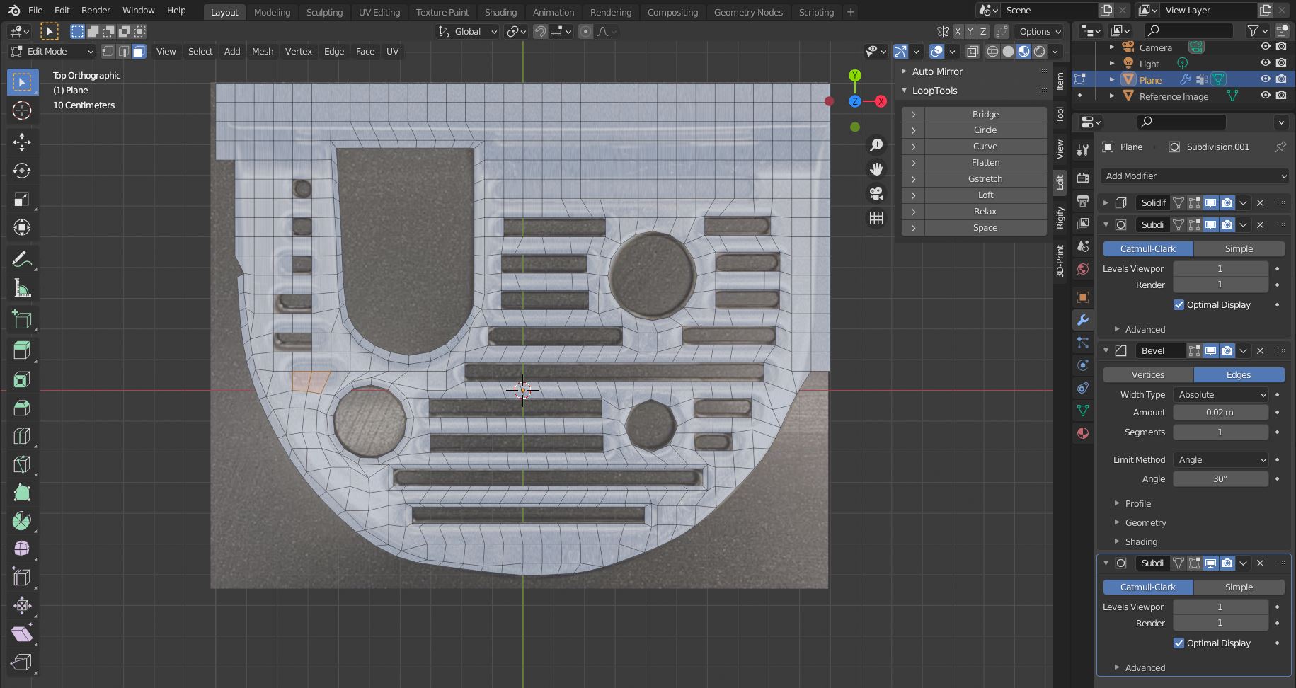
An approach without Booleans is to model this plate from a subdivided plane and then add some modifiers. Lay the mesh over the reference image and remove the square faces where the holes should be:

screenshot 1

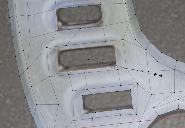
Then either extrude (E, S) and scale a support loop:

extrude and scale

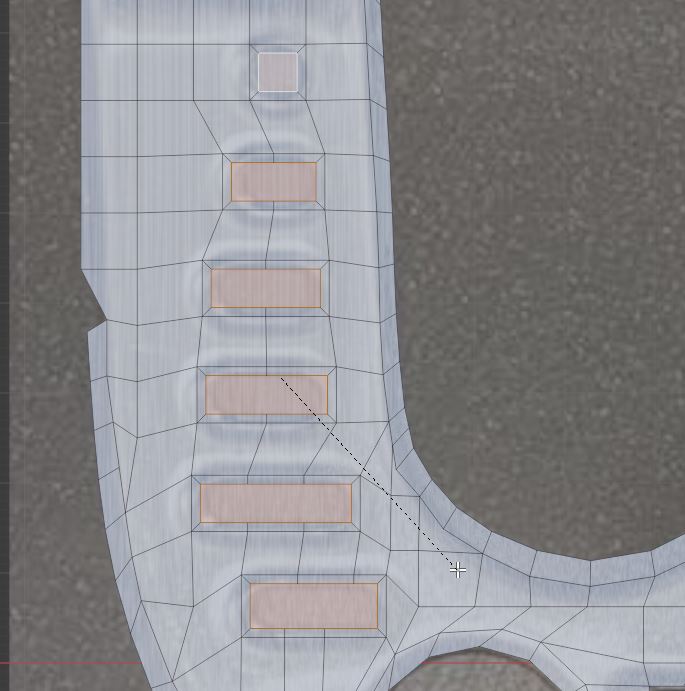
-or- fill (F), inset (I) and remove the face. Later creates an edge with even width. On the outer edges of the plate you need to use Extrude:

inset example

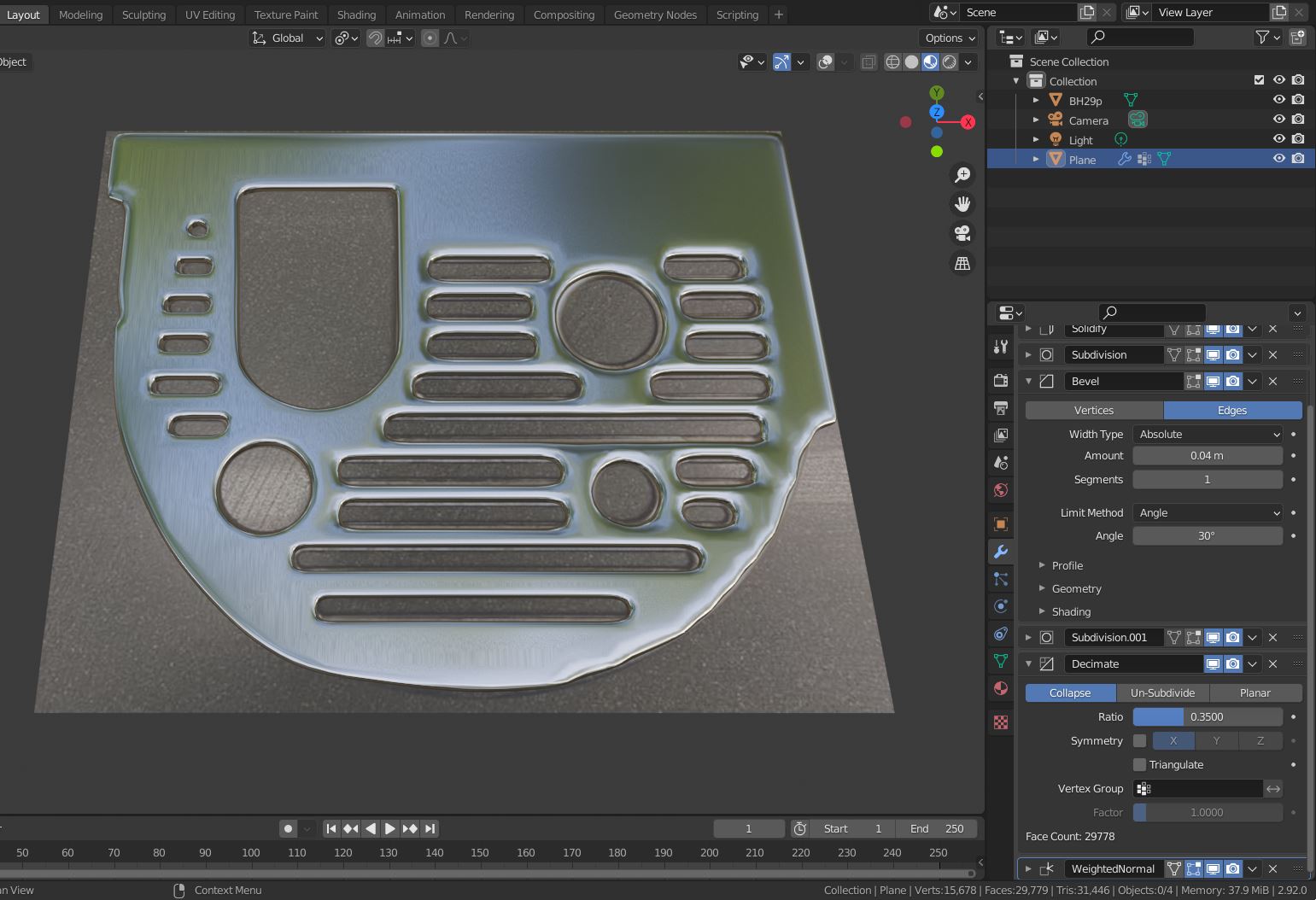
For comparison, the left/bottom area has extruded/inset extra support loops, the right/top area has none and is a bit jagged:

final model

The round holes can be created with the Mesh:LoopTools add-on that ships with Blender (screenshot 1). The edges can be smoothed with the Relax operation of the LoopTools.

$\endgroup$
2
  • 1
    $\begingroup$ Good suggestion, way cleaner this way. $\endgroup$
    – brockmann
    Commented Sep 27, 2021 at 17:48
  • $\begingroup$ Thank you so much for the clear explanation, and the explanatory images! Not all heroes wear capes :-) The solution is indeed far better than the boolean approach, and the relax feature + insets solve it perfectly IMO. Cheers! $\endgroup$ Commented Sep 28, 2021 at 19:50

You must log in to answer this question.

Not the answer you're looking for? Browse other questions tagged .