1
$\begingroup$

I have a following setup: a curve aligned to one of the main axes (e.g. z), so every vertex of that curve has z = same value. I want to extrude and offset the new vertices along the direction locally given by the average normal vector of the two adjacent edges projected onto the plane of the curve (gives two options, I want to be able to choose the direction) by the same constant offset so the resulting thickness is the same. I know this must be possible mathematically, because when I choose two adjacent edges, change the transform orientation from global to normal and move in 'z' direction, it moves exactly according to the average normal of those two edges. I hope this would be possible for individual vertices and their two shared edges.

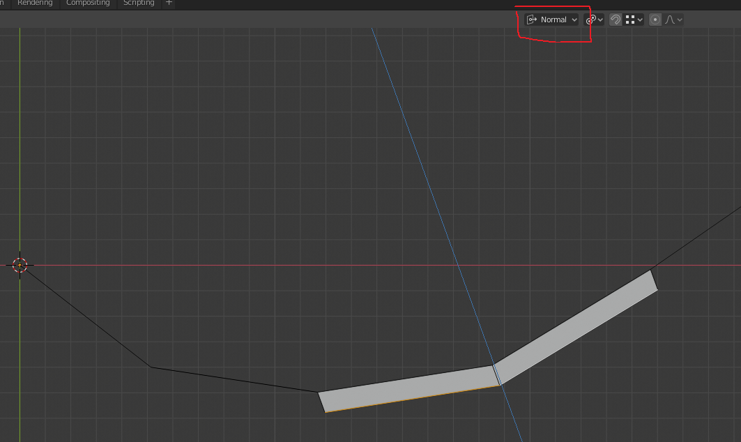
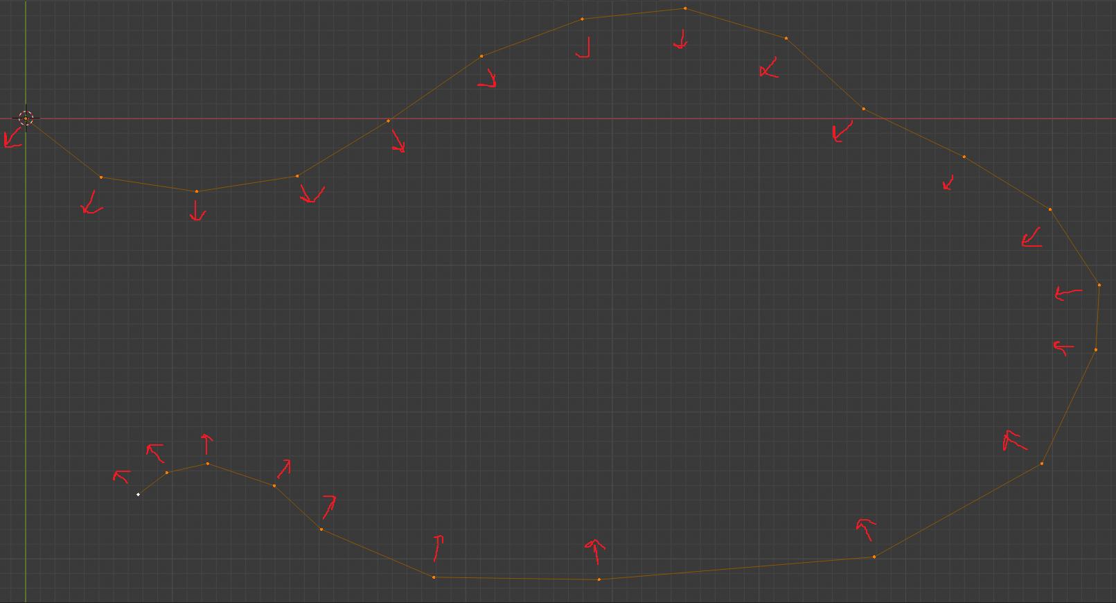
I hope this picture demonstrates what I want...

what I want

Here is how it works for two adjacent edges...note that the vertex in the middle gets displaced along the exactly correct direction, which is the average direction of the normals of the two edges next to it. However, the vertices on either end are in slightly wrong direction...

normal direction for two adjacent edges

Is this even possible? Did I miss something obvious in the "Extrude region and move" menu? I also tried solidify (which also warns the user that faces are needed for useful output) and bevel, none of which produced the desired effect. Thanks.

$\endgroup$
2
  • $\begingroup$ Related blender.stackexchange.com/questions/103093/… $\endgroup$
    – batFINGER
    Commented May 6, 2020 at 23:03
  • $\begingroup$ First of all, my Blender (2.82a, very recent) does not have "edit tools 2" add-on. I assume it's merged within the mesh tools? Secondly, when I press W, I don't get any tools box, I instead see the circular select tool (one that is also activated with 'c'). I think Blender is evolving so quickly that that answer does not apply anymore (user Alexander Podgayko claims this works in 2.79) :/ $\endgroup$
    – user16320
    Commented May 6, 2020 at 23:09

2 Answers 2

4
$\begingroup$

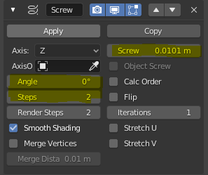
This feels hacky but you can manage to get the result with modifiers. Works best with the 2.82+ version for the weld modifier. First, add a screw modifier set to Z with 2 steps and an angle of 0°, and a very low screw.

enter image description here

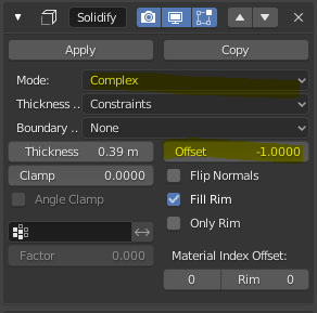
Next, add a solidify modifier set to "complex" mode and set the offset either to 1 or - 1

enter image description here

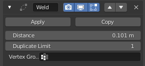
If you mind having a 3D mesh, you can merge each vertex to its closest one to go back to 2D, with a merge modifier. Set the threshold to the same value as the screw modifier.

enter image description here

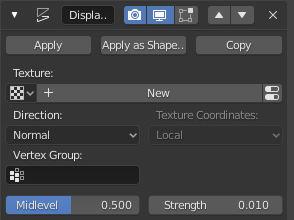
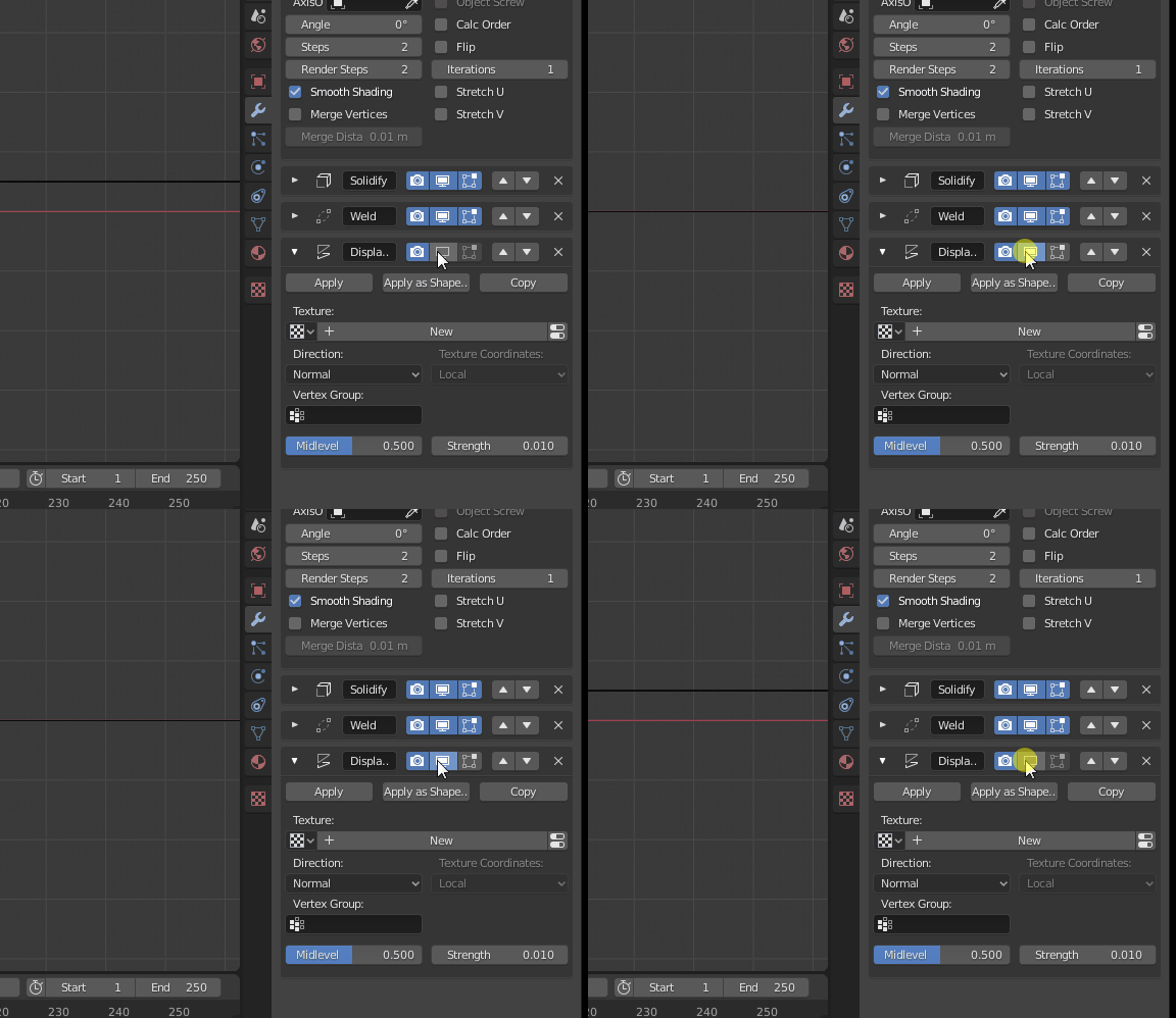
This can not be the case depending on how the merge modifier works but on my end the mesh ends up slightly above the XY plane (ie the modifier keeps the "screwed" vertex instead of the original one), so you can add a displace modifier to put it back to Z = 0

enter image description here

enter image description here

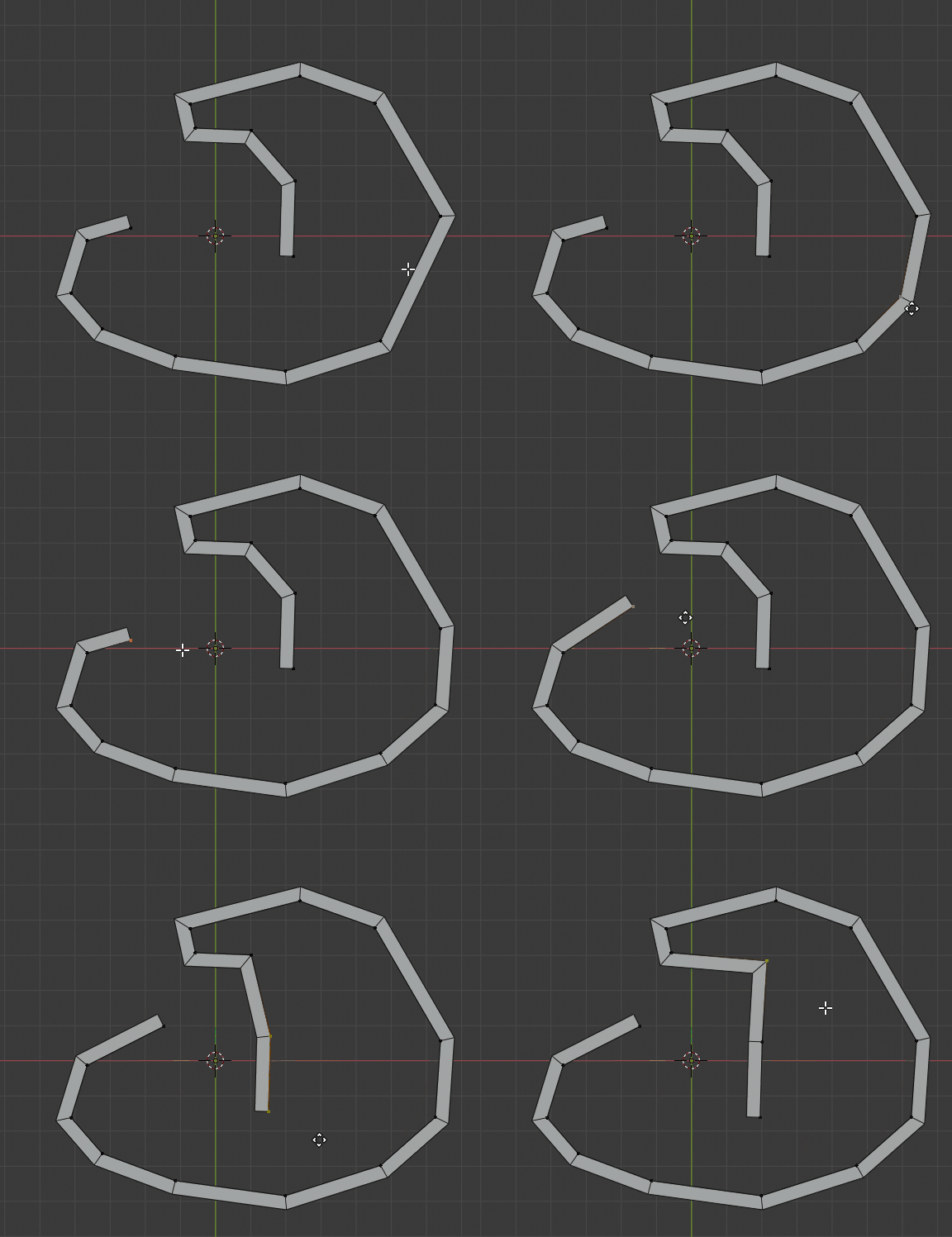
Result :

enter image description here

$\endgroup$
2
  • 1
    $\begingroup$ This is COOL! :O and modifiers can be applied to vertex groups so I don't even have to worry about applying a modifier to a larger mesh with a part that needs to be "pathified"...well done! $\endgroup$
    – user16320
    Commented May 7, 2020 at 16:59
  • $\begingroup$ Glad it helped ! Unfortunately the Screw modifier can't be applied to certain vertex groups... (yet), and it will destroy faces elsewhere. But the other ones can ! :) FYI the vertex group option in the weld modifier doesn't work in 2.82 but it is fixed in version 2.83 and up $\endgroup$
    – Gorgious
    Commented May 7, 2020 at 18:13
6
$\begingroup$

Two possible workflows I can quickly think of.

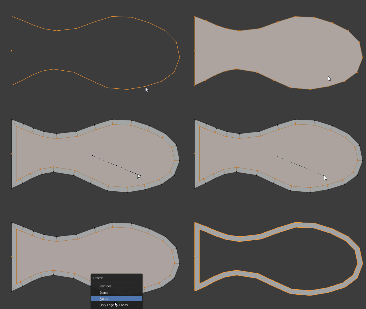
  1. Select all edges in Edit Mode, press F to make a face then inset it with i. Deal with the leftover "closing loop" in the end manually.

enter image description here

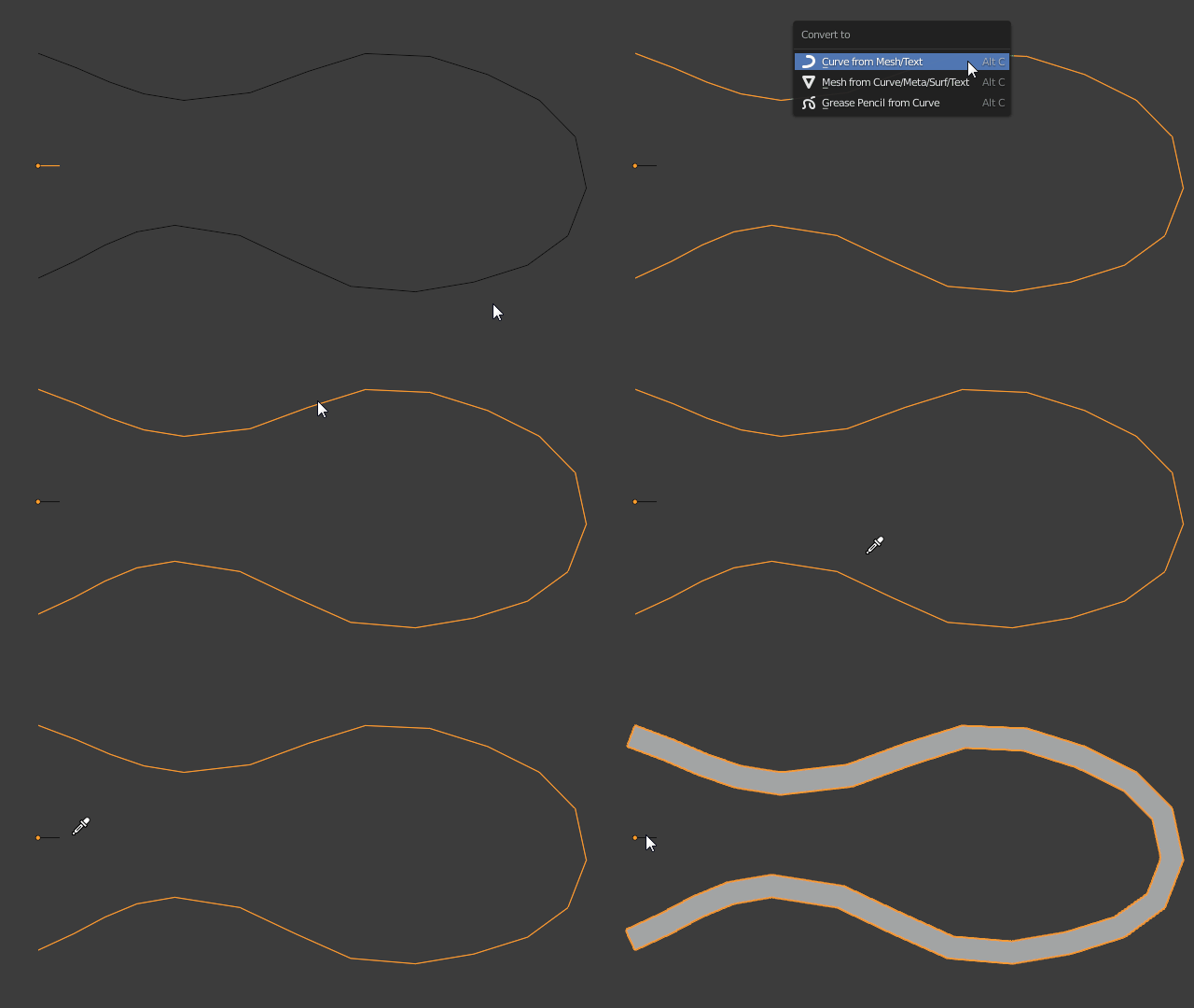
  1. Just convert the edges into an actual Bezier Curve object with Alt + C > Curve from Mesh, then from the Properties Window > Curve Object Data Geometry > Bevel add a second curve as Bevel Object comprised of a single edge in $XY$ direction. Make sure the main curve is set to 2D to get consistent width, and control width with either Curve Radius, directly adjust the bevel object, or with a Taper Object.

enter image description here

$\endgroup$
2
  • $\begingroup$ I like the option 1! (second one is rather unsuitable, as the curve is usually a part of a bigger mesh so converting to bezier is not very convenient, as one would have to first separate it and then rejoin after the deed is done). Any way to deal with the end vertices (you can see that in your example they are pointing wayyy inwards, which is caused by the normals at that point. One solution would be, I guess, add a dummy vertex on each end by extruding and edge sliding away (with clamping turned off)...that way the last vertex (the original one) will go along the normal direction. $\endgroup$
    – user16320
    Commented May 6, 2020 at 23:38
  • $\begingroup$ "One solution would be, I guess, add a dummy vertex on each end by extruding and edge sliding away" As I was reading your comment I was thinking the same, should work fine $\endgroup$ Commented May 6, 2020 at 23:48

You must log in to answer this question.

Not the answer you're looking for? Browse other questions tagged .