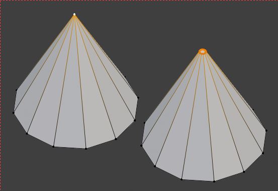
Hi, I am attempting to make a British Spitfire to the best of my ability, but I have encountered a problem. I have used a Cone Mesh to try and replicate the spinner of a British spitfire, but I cannot get the round shape that I need for it to look realistic. I will provide a picture below.
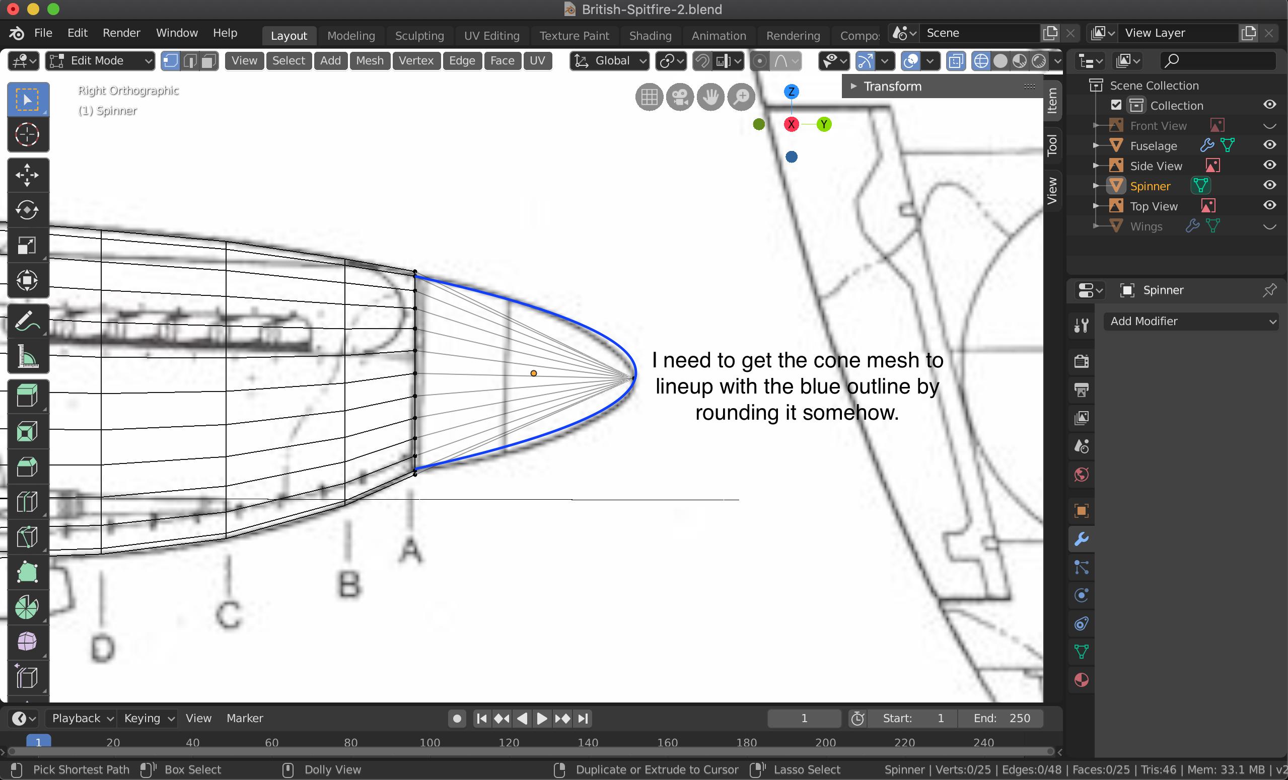
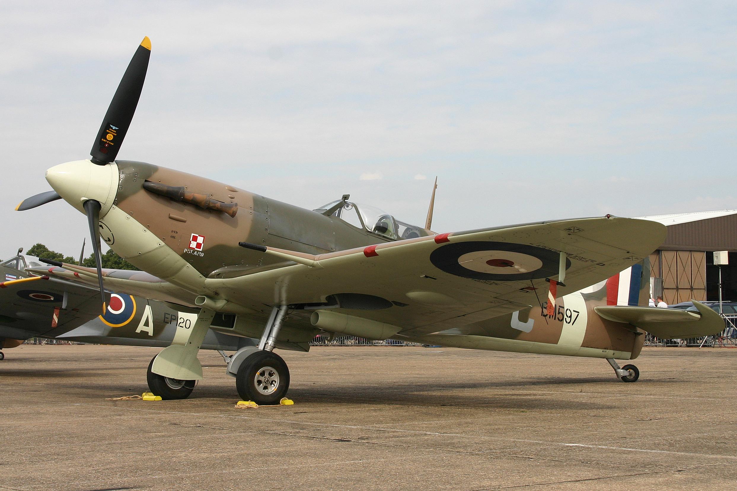
Once I am finished with the base shape of the spinner, what would be modeling steps to making it look more detailed? Below is a picture of a British Spitfire spinner.
3 Answers
Here are the steps I would take to model that:
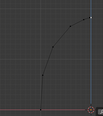
1: construct a base set of vertices from one side of the rounded top, like so:
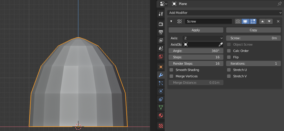
Add a screw modifier: (make sure it is lined up to the axis for this part).
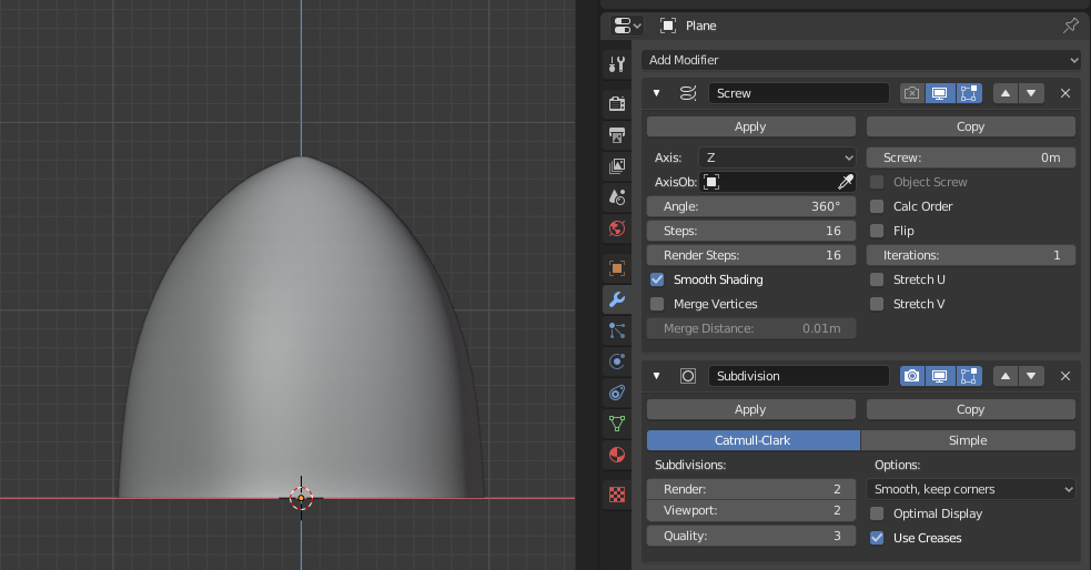
Then finally add a subidivision surface modifier to make it higher poly:
I hope that is what you are looking for. You can just adjust the vertices (or line them up to your image) to get the curve you want. When you are done, you can apply the modifiers and put it on your plane.
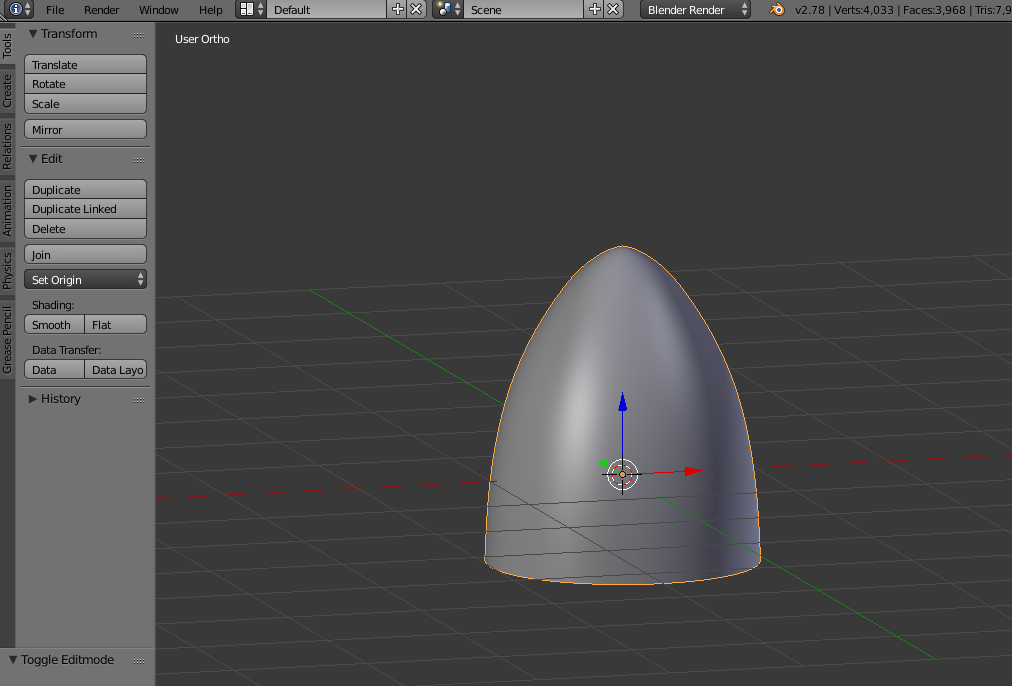
Split a UV Sphere in half, scale it up on the z axis, and add a subsurf modifier with smooth shading ...with the right scaling and editing you should get the desired result.
Here's how I would go about it, from a sub-d point of view, aiming for least work and most accuracy.
Two things to notice: 1. The nosecone is truncated, so there won't be nasty shading problems at the tip. 2. There are 3 blades on the propeller. At some stage, holes will have to be cut for them, so the number of sides on the cone should be divisible by 3.
(I'm working in XY, Z up.. you may have to flip axes mentioned here)
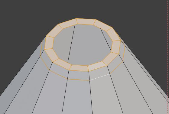
- Create a 12-sided cone, and CtrlShiftB bevel the vertex at the tip to the dimensions of the reference
- I inset the new face, and CtrlR cut in a holding loop close to the rim.
- X delete the inner face
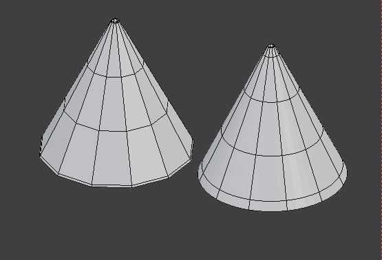
- Do the same to the base of the cone
- CtrlR cut in a couple of intermediate loops, and
- CtrlKeypad 2 assign a Sub-d Surface modifier, level 2
- Now, working under the modifier, showing in Edit Mode, with cage conforming (switches in the modifier)
- A combination of GG sliding the intermediate loops up and down the cone, and..
- SShiftZ scaling the loops in XY..
..should enable you to capture the curvature of the cone.
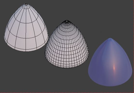
The illustration shows:
- How the cone appears while editing, with the modifier set to 'Optimized Display'
- The underlying topology after subdivision
- The finished cone
Later, you will be able to cut out a 1/3 segment of the cone, and give it a rotational array, so you can work on the details in one third, and have the edits automatically propagated to the rest.

