7
$\begingroup$

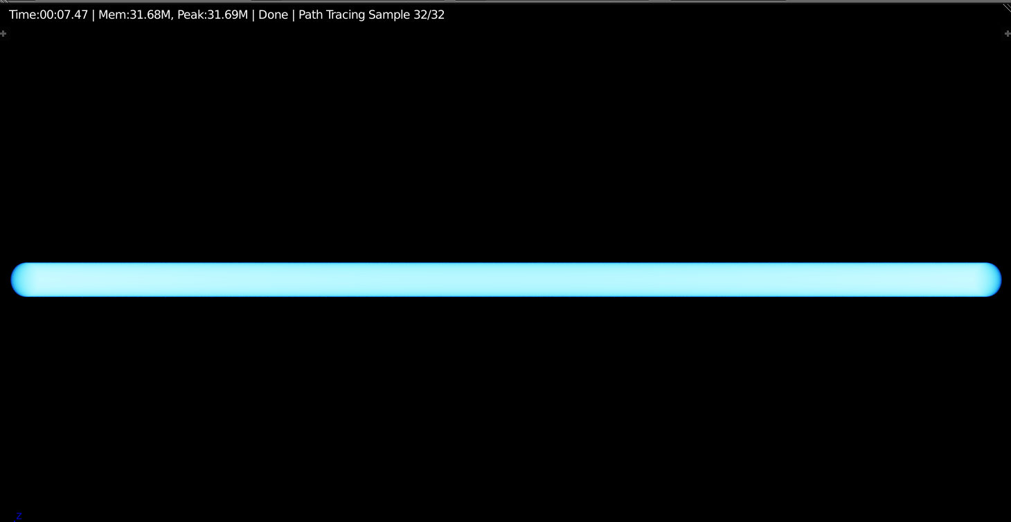
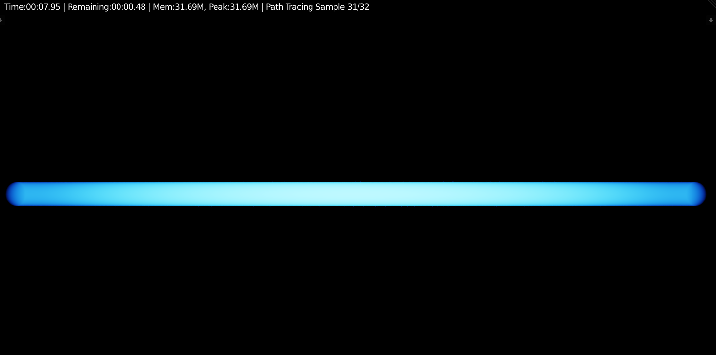
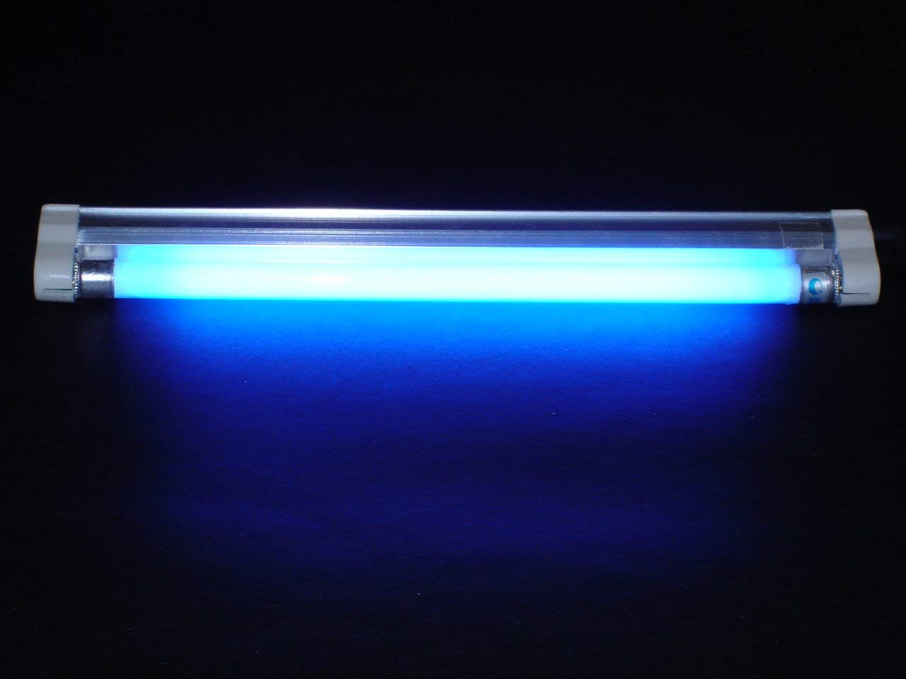
I have a principled shader with the transmission set to 1.0 plugged into the surface input of my material output. I have an emission shader plugged into the volume input. I'd like the material to grow brighter the deeper into the mesh it is, somewhat akin to the image below.

How would I make my emission be stronger on the inside of a mesh based upon volume? This preferably would not need to include any custom scripts.

EDIT This has absolutely nothing to do with the "duplicate question" candidate. I'm speaking of mesh volume, not the loudness of an audio file.

enter image description here

$\endgroup$
8
  • $\begingroup$ Nope. No it's not. $\endgroup$
    – Legoman
    Commented Jul 7, 2018 at 15:33
  • $\begingroup$ I apologize. I misread. $\endgroup$
    – Leander
    Commented Jul 7, 2018 at 15:52
  • $\begingroup$ @Legoman Are you animating or using the game engine? $\endgroup$
    – VorTechnix
    Commented Jul 18, 2018 at 0:43
  • $\begingroup$ @TechTornado I'm using Cycles. $\endgroup$
    – Legoman
    Commented Jul 18, 2018 at 1:51
  • 1
    $\begingroup$ Please can you better define “based on volume”? How should the emission vary based on volume? Eg, Is it a single emission value for the whole volume that varies based on the overall volume (so that the total amount of light emitted could be kept constant, just spread over a larger volume) or should the emission vary based on depth below the surface (such as blender.stackexchange.com/a/89262/29586)? $\endgroup$ Commented Jul 18, 2018 at 8:05

5 Answers 5

4
+50
$\begingroup$

I don't think this is possible with just nodes - there are no facilities to determine the depth below a surface. One solution is to use OSL to add a new node that can 'probe out' the surrounding geometry as in this answer as follows :

Enable Open Shader Language in the Render settings, open a Text Editor window, click New to create a new text block, set the name to something like 'mesh_proximity.osl' and paste the following code :

shader volume_meshproximity(
    vector Point = P,
    int Iterations = 1,
    output float Min_Distance = 0.0,
    output float Max_Distance = 0.0,
    output float Avg_Distance = 0.0
    ) {

    float x;
    float y;
    float z;
    vector rand;
    float scale = 5000.0;
    float sum_dist = 0.0;
    float max_dist = 0.0;
    float min_dist = 0.0;
    float Distance = 0.0;

    for (int loop = 0; loop < Iterations; loop++)
    {

        rand = noise(Point*scale,loop*scale);
        x = rand[0] - 0.5;
        y = rand[1] - 0.5;
        z = rand[2] - 0.5;

        if(trace(Point,normalize(vector(x,y,z))))
        {
            getmessage("trace", "hitdist", Distance);
            //getmessage("trace", "N", Normal);
            //getmessage("trace", "hit", Hit);
        }

        if (loop == 0)
        {
            sum_dist = Distance;
            max_dist = Distance;
            min_dist = Distance;
        }
        else
        {
            sum_dist = sum_dist + Distance;

            if (Distance > max_dist)
            {
                max_dist = Distance;
            }

            if (Distance < min_dist)
            {
                min_dist = Distance;
            }
        }
    }

    Max_Distance = max_dist;
    Min_Distance = min_dist;
    Avg_Distance = sum_dist / Iterations;
}

In the node editor add a Script node and set it to the text block you have just created. If all is well the OSL node will be compiled and you should have a new node that can be used in a Volume shader and provides Min, Max, and Average distance. This can be used as in the following material :
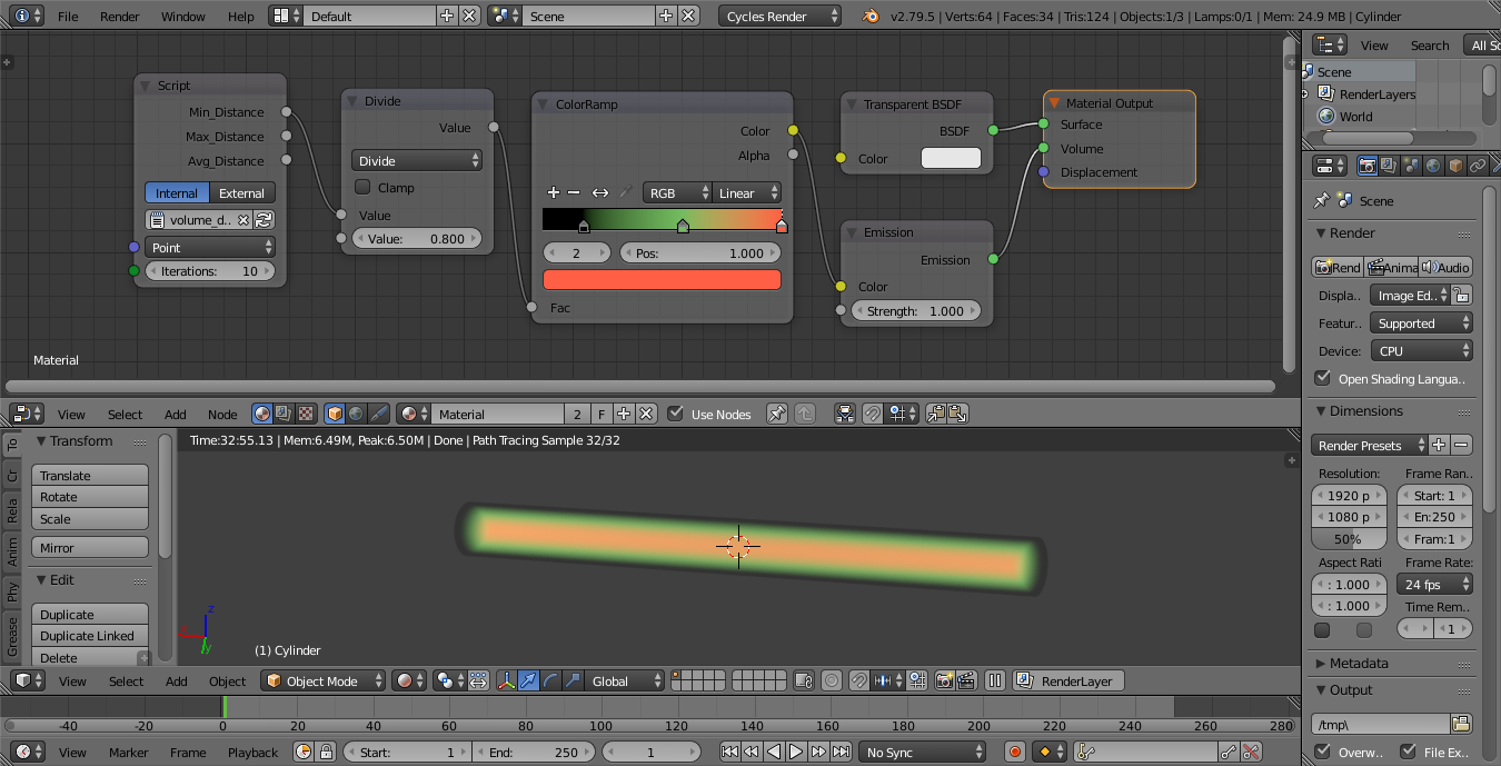
material and result

The new node projects rays from the sample point in the volume, determining how far they have travelled until they hit a surface. The number of rays is controlled by the Iterations - more rays results in less noise but takes longer to calculate. The Min_Distance returns the shortest distance for any of those rays, the Max_Distance the longest distance for any of those rays, and the Avg_Distance the average distance for all of those probe rays. Adjust the Divide node to scale the gradient and adjust the color ramp to adjust how the emission changes below the surface - similar can be done to control emission strength as well as color.

Here's my final render using the depth to control emission strength :
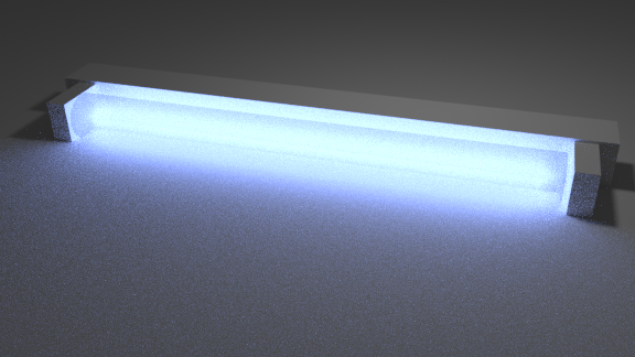
final rendered

Blend file included

I have tried other solutions, without resorting to OSL (since OSL is not GPU compatible - you'll only be able to render on CPU) - such as using a smoke simulation to diffuse smoke out of the volume to achieve a gradient - but so far without success.


One promising alternative solution is to use a Point Density texture acting on a large number of particles distributed evenly over the surface using Grid distribution. However, you do need to increase the resolution quite high.

To achive this, add a Particle System to the mesh and set it to Emit From Faces with Grid enabled and Hexagonal Grid. Increase the particle grid Resolution until you have enough particles to give a dense enough covering (you might need to click in the field and type a values as the 'soft' limit is only 50. Then add the create the following nodes for the material :
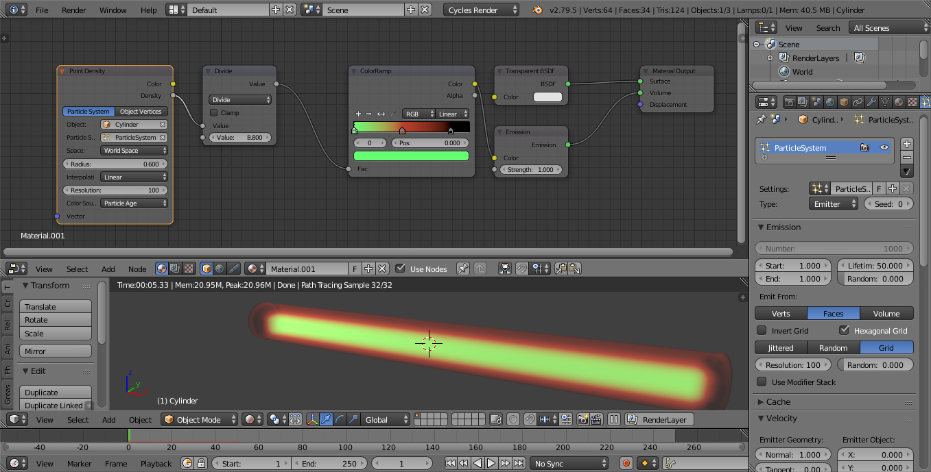
gradient using point cloud

Set the Object to your mesh and select the Particle System with Space set to 'World Space'. You can vary the Radius and Resolution to vary the effect. The Divide node can be used to vary the distance of the effect of the Color Ramp.

$\endgroup$
2
  • $\begingroup$ Am I right in thinking we have absolutely no access to the (number/length of sampling steps taken so far) by the volume-rendering algorithm? Naively, you would have thought they would be quite easy to expose in the Light Path node.. $\endgroup$
    – Robin Betts
    Commented Jul 19, 2018 at 12:25
  • 1
    $\begingroup$ @RobinBetts It would certainly be nice to have but, no, I don't believe we have access to those. For volumes any of the potentially useful Light Path values are unaffected. However, even if we did have them it would only partly help - for a ray passing through a volume we'd be able to tell how far into a volume it had travelled but not how far out it had left to go. $\endgroup$ Commented Jul 19, 2018 at 12:48
2
$\begingroup$

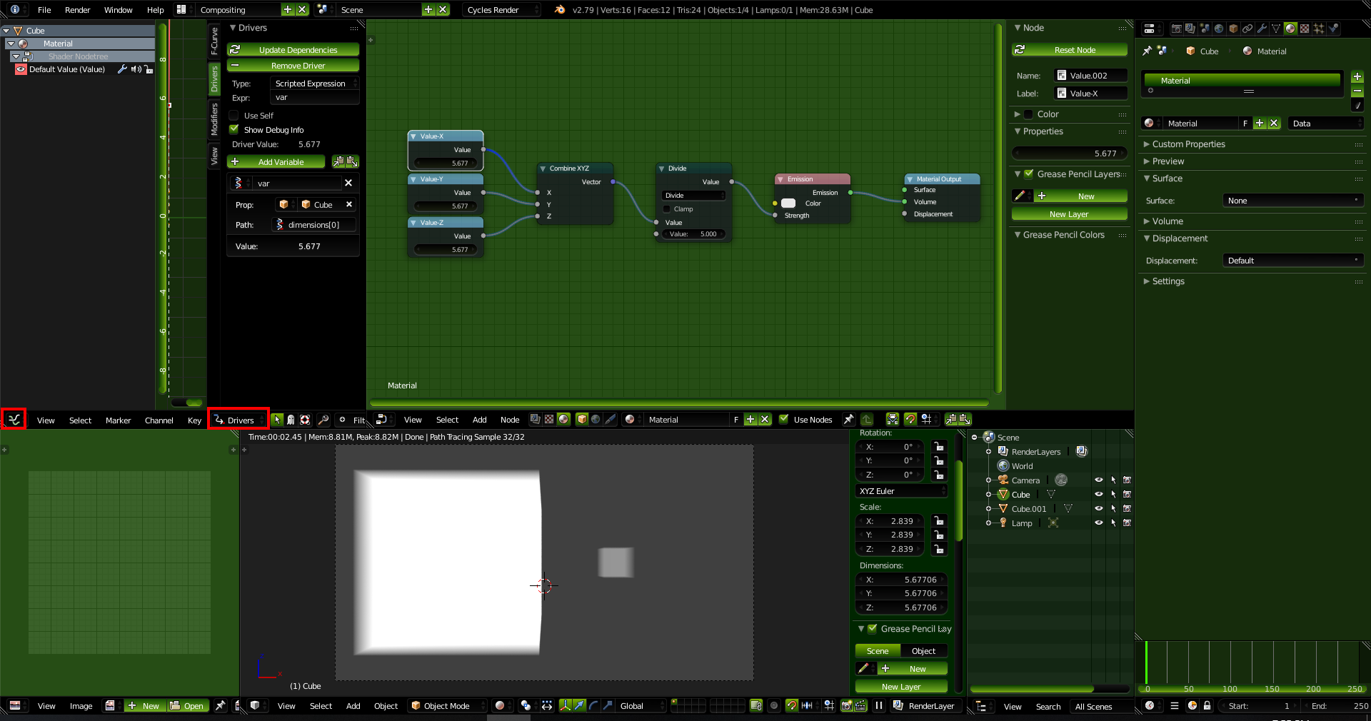
My previous answer was based on scale, however I found a driver-based (not script) answer that should solve your problem.

However you need to Enable Autorun if you have not already done so in order for that answer to work.

Here are some screenshots of my setup. The blend file is below them.

Add driver

The driver paths for the dimensions are as follows:

X:dimensions[0]

Y:dimensions[1]

Z:dimensions[2]

Dimensions

And here is my finished setup (note that you can edit drivers in the Drivers view of the Graph Editor):

final setup

$\endgroup$
1
$\begingroup$

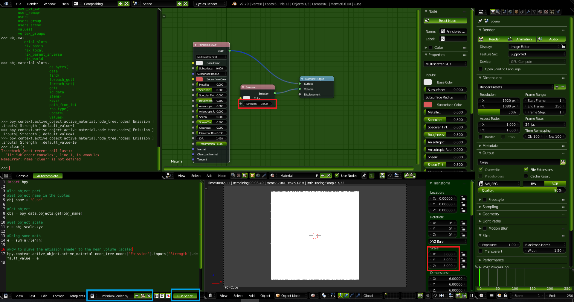
Here, have a code block. Copy and paste it into notepad and save it as "emission-scaler.py". Load it into the text editor in Blender and then press the "Run Script" button whenever you change the scale and voila, the emission is set.

import bpy

#The object part
#Set object name in the quotes
obj_name = "Cube"

#Get object
obj = bpy.data.objects.get(obj_name)

#Get object scale
n = obj.scale.xyz

#Doing some math
e = sum(n)/len(n)

#Now to slave the emission shader to the mean volume (scale)
bpy.context.active_object.active_material.node_tree.nodes['Emission'].inputs['Strength'].default_value = e

Here is a screenshot of the script at work. Also the last line of that code came from here. Script in Blender

$\endgroup$
1
  • $\begingroup$ have to love comments like #Doing some math $\endgroup$
    – Nathan
    Commented Jul 18, 2018 at 0:25
1
$\begingroup$

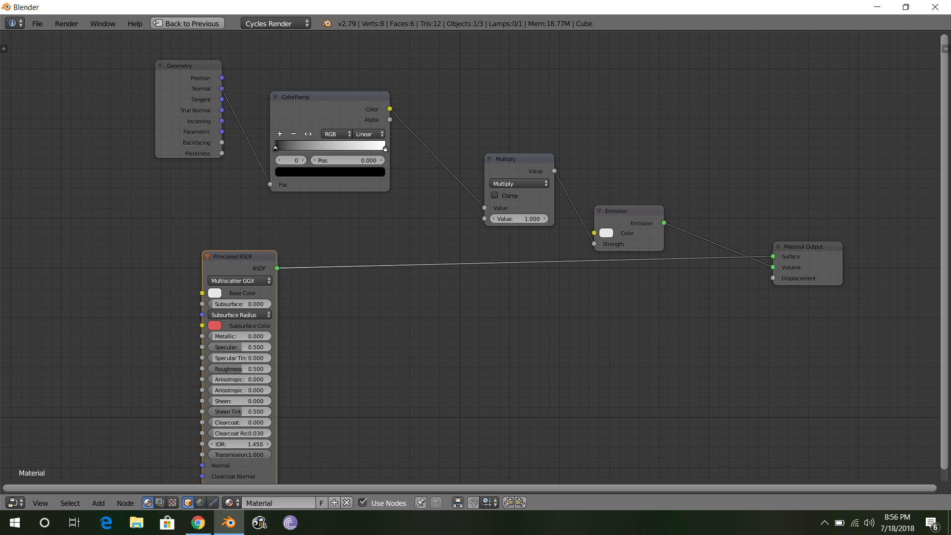
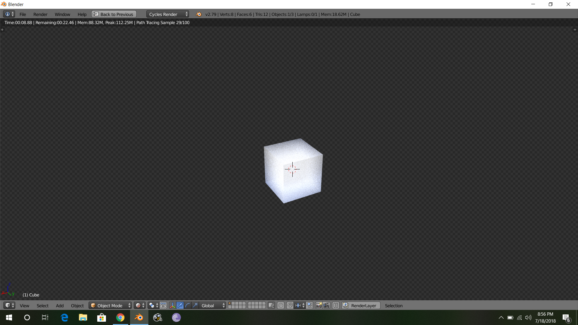
so here is my setup. Let me know if this works for you? This is simple and i think its self explanatory! You can use the color ramp to change the depth and use the multiply node to give the strength to the emission shader!

enter image description here

enter image description here

$\endgroup$
1
  • 2
    $\begingroup$ Can you explain how this works? AFAIK, the Normal output of the Geometry node does not work volumetrically. Also, the ColorRamp appears to have no purpose, as it is left in its default state, and anything it does would already be done by the multiply node. $\endgroup$ Commented Jul 18, 2018 at 17:37
1
$\begingroup$

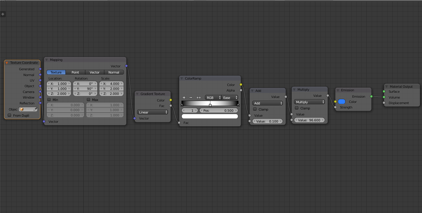
Given the image you post and the explanation about increasing the emission strength based on the mesh volume I created this Node Setup:

enter image description here

So how does it work?

Hacking the mesh volume

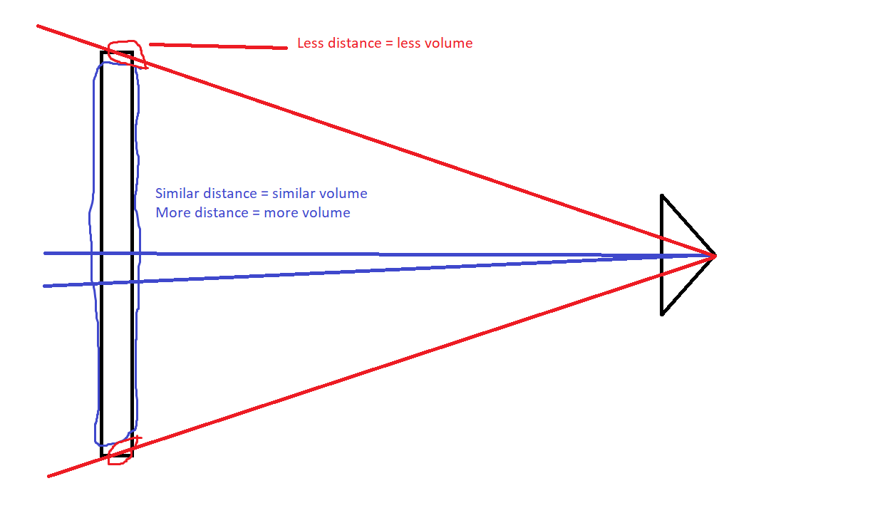
Altough is true that in the center of the cylinder the volume is greater than in the borders, the difference is almost null

enter image description here enter image description here

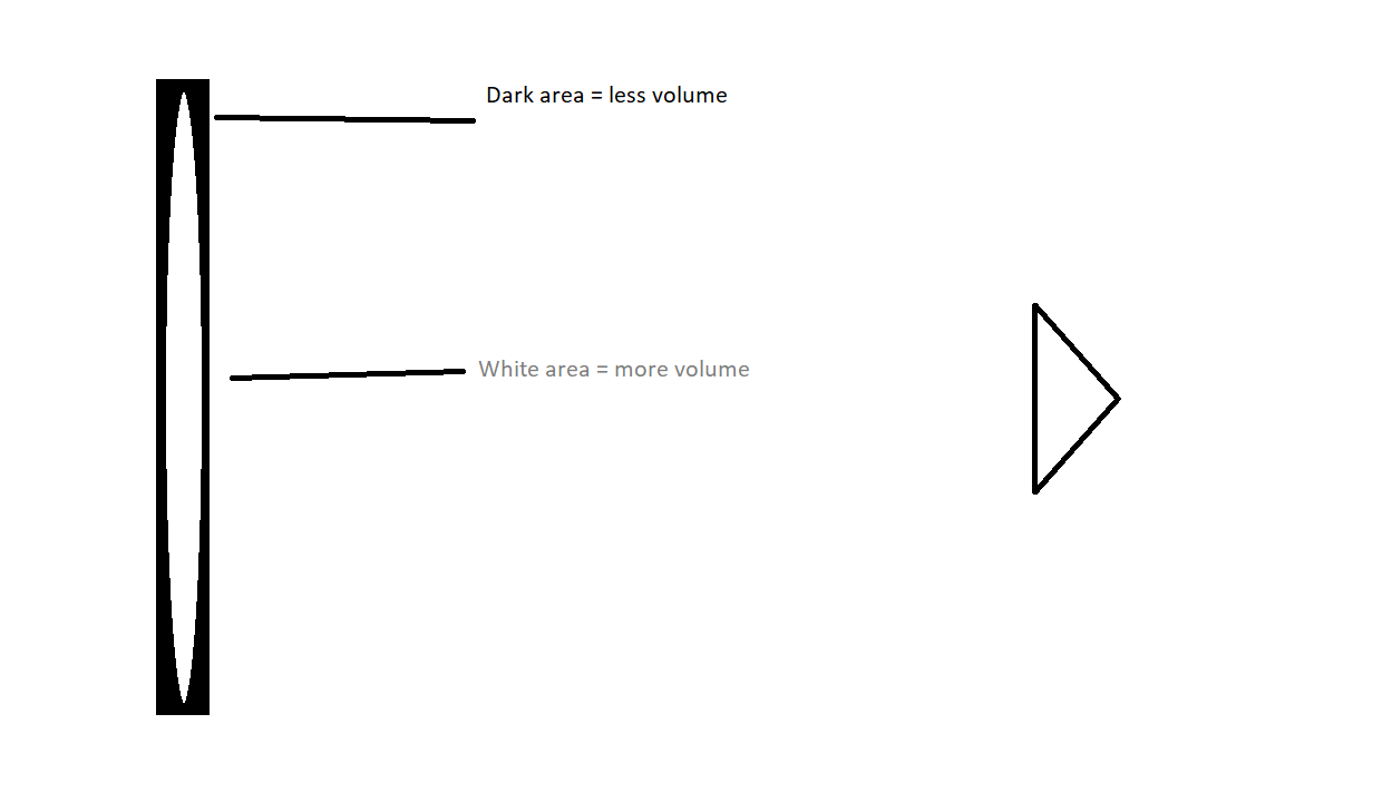
Then we can use a gradient texture to increase the volume only in the center of the cylinder

enter image description here enter image description here

It can seems like cheating and no physically accurate, but it's not far from reality, since in neon lights the halogen gas is not evenly distributed

$\endgroup$
2
  • $\begingroup$ Yeah volumetrics can only alter density of emission based on a texture, not geometry. $\endgroup$
    – 3pointedit
    Commented Jul 19, 2018 at 4:56
  • $\begingroup$ Add a Layer Weight influence to this, to make tangential faces darker, and you've got an efficient simulation of neon tubes, the way I remember doing it before volume shaders were practical. $\endgroup$
    – Robin Betts
    Commented Jul 19, 2018 at 10:22

You must log in to answer this question.

Not the answer you're looking for? Browse other questions tagged .