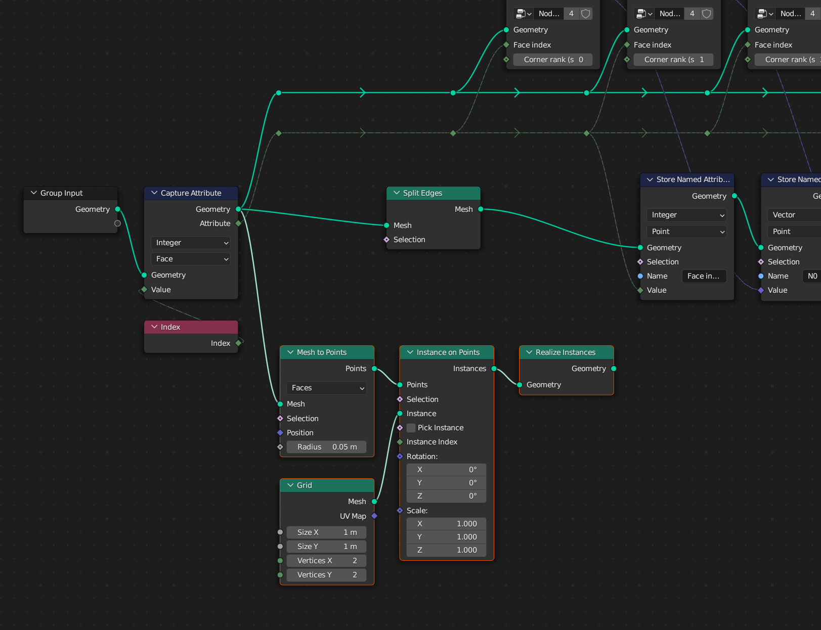
Starting with geometry:
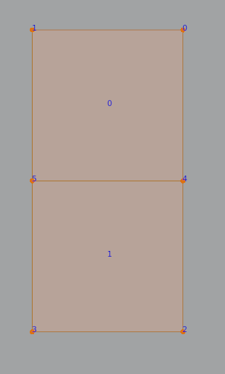
Vertices: [(1,2), (0,2), (1,0), (0,0), (1,1), (0,1)]
Faces: [(0,1,5,4), (4,5,3,2)]
The indices of vertices defining faces also tell us about the corners. We can confirm the order is the same (the above order I took from Python API), by using a viewer:
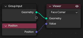
For example The first 4 corners belong to the first face, and then corners # 4,5,6,7 belong to the 2nd face, so the corner #7 is the last corner of the 2nd face, as we can see above the last corner is associated with vertex index #2, and the vertex index #2 should have coordinate (1,0), and the position matches:

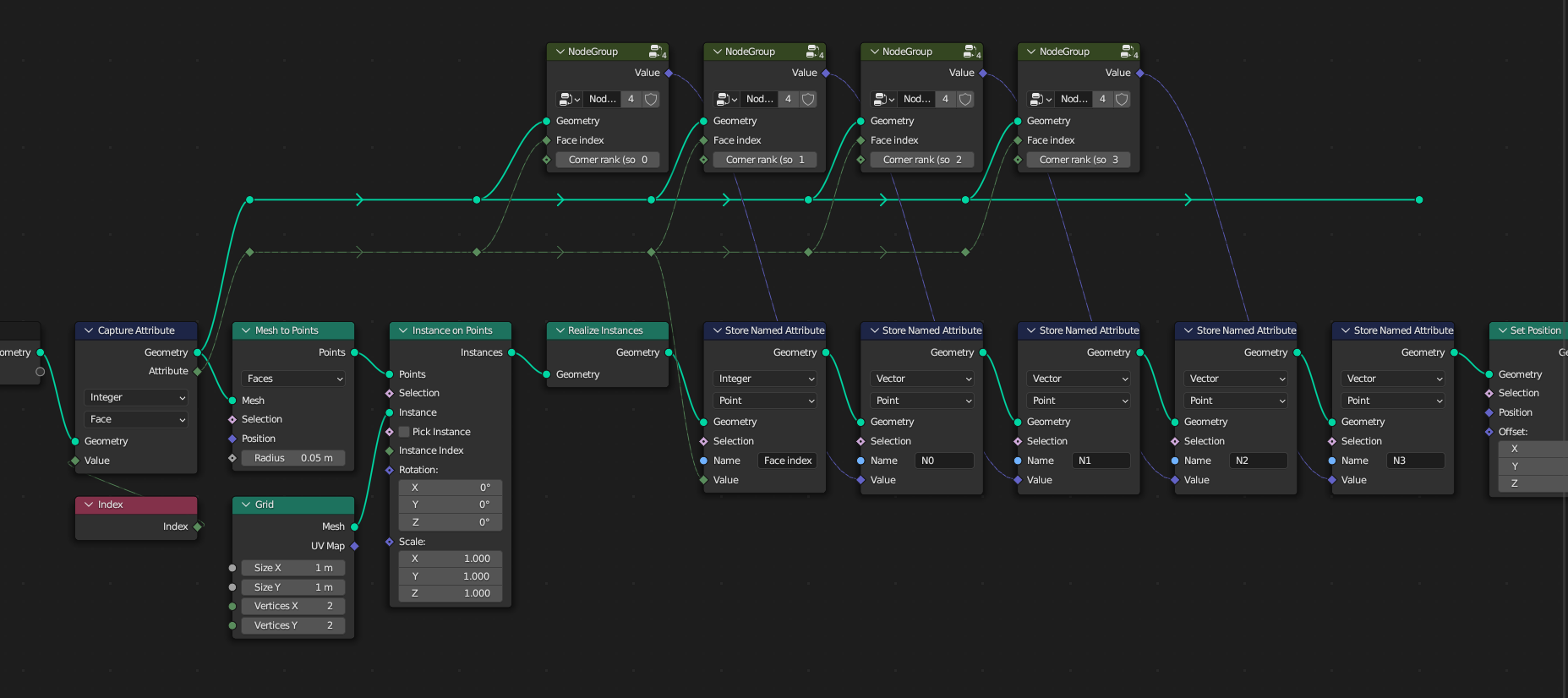
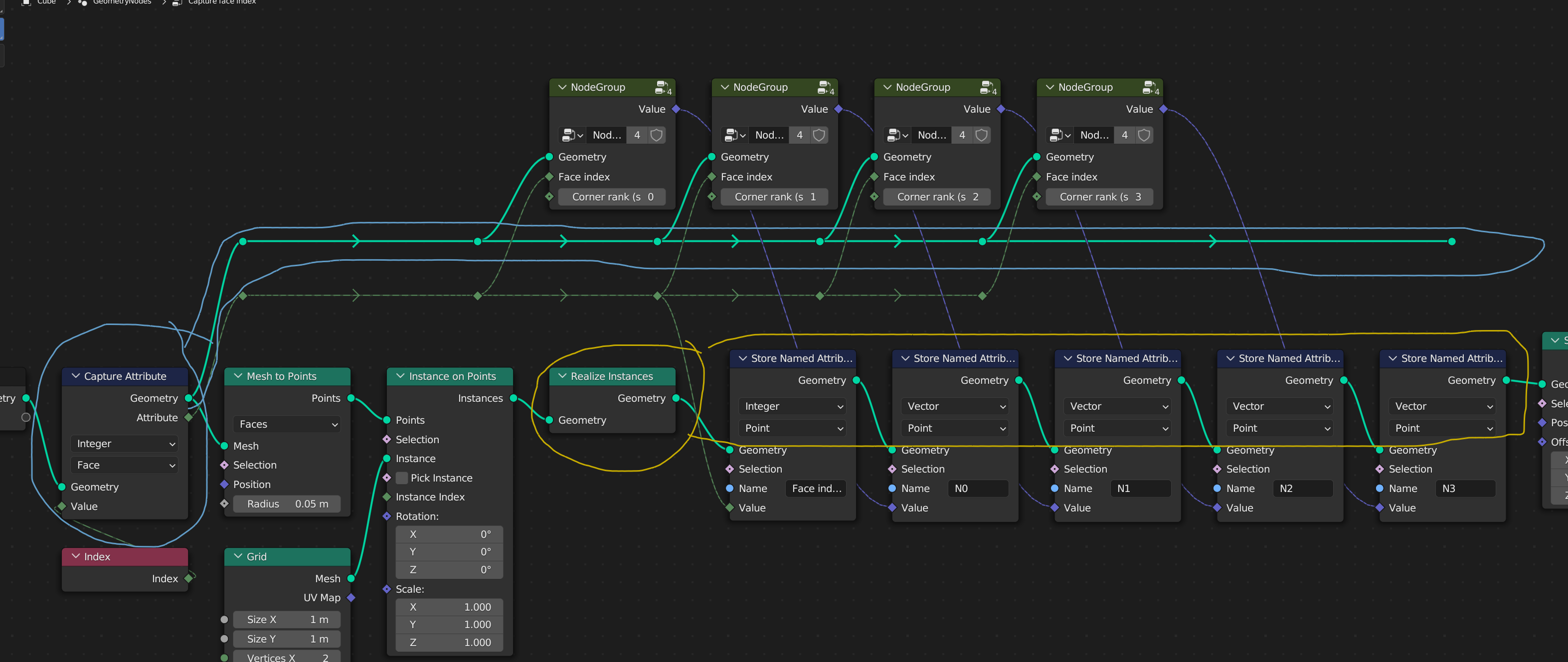
You pass that geo to Capture Attribute and capture index:
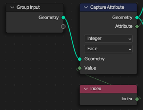
It's pretty straight-forward, you now have an array for faces: [0, 1]
Vertices: [(1,2), (0,2), (1,0), (0,0), (1,1), (0,1)]
Faces: [(0,1,5,4), (4,5,3,2)]
Faces_anon_attr: [0, 1]
Now you convert those faces to points using Mesh to Points, so the mesh data is now:
Points: [(0.5, 1.5), (0.5, 0.5)]  - taken from centers of faces
anonymous_attribute: [0, 1]  - simple copy
You also create a Grid:
Vertices: [(-0.5,-0.5), (-0.5,+0.5), (+0.5,-0.5), (+0.5,+0.5)]
Faces: [(0, 2, 3, 1)]
Now you implicitly convert the grid to an instance, let's call it my_quad, and spawn that Instance on the Points:
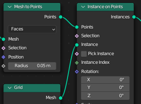
Your geometry now:
Instances: ['my_quad', 'my_quad']
Instances_pos: [(0.5, 1.5), (0.5, 0.5)]  - simple copy from points
Instances_anonymous_attr: [0, 1] - simple copy from points
And now you Realize Instances, so the geometry becomes:
Vertices: [(-0.5,-0.5), (-0.5,+0.5), (+0.5,-0.5), (+0.5,+0.5)] - from `my_quad`
       +    (0.5, 1.5)   (0.5, 1.5)   (0.5, 1.5)   (0.5, 1.5)  - from instance pos

Verts ctd:[(-0.5,-0.5), (-0.5,+0.5), (+0.5,-0.5), (+0.5,+0.5)] - from `my_quad`
            (0.5, 0.5)   (0.5, 0.5)   (0.5, 0.5)   (0.5, 0.5)

=

Vertices: [(0,1), (0,2), (1,1), (1,2)] + [(0,0), (0,1), (1,0), (1,1)]
Faces: [(0, 2, 3, 1)] + [(4, 6, 7, 5)] - taken from `my_quad` but offset by domain_size * instance index

Vertices_anon_attr: [0, 0, 0, 0] + [1, 1, 1, 1] - for each vertex from `my_quad` duplicate data from instance.
Edges_anon_attr: same as above
Corners_anon_attr: same as above
Faces_anon_attr: [0] + [1] - same logic, but `my_quad` had only 1 face.
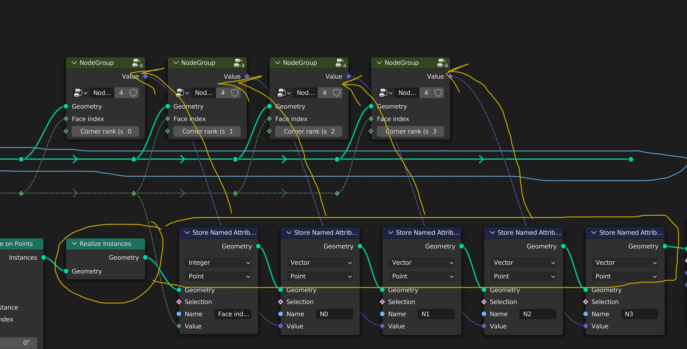
Your first Store Named Attribute is easy:

So you create Face index attribute in Point domain. You're connecting a field from face domain, but I already calculated all possible interpolations above, so regardless when Blender decides to calculate it, it will be the same stuff as listed above as Vertices_anon_attr but this time with a name:
Vertices: [(0,1), (0,2), (1,1), (1,2), (0,0), (0,1), (1,0), (1,1)]
Faces: [(0, 2, 3, 1), (4, 6, 7, 5)]

Vertices_anon_attr: [0, 0, 0, 0, 1, 1, 1, 1]
Vertices["Face index"]: [0, 0, 0, 0, 1, 1, 1, 1]
Edges_anon_attr: same as above
Corners_anon_attr: same as above
Faces_anon_attr: [0] + [1] - same logic, but `my_quad` had only 1 face.
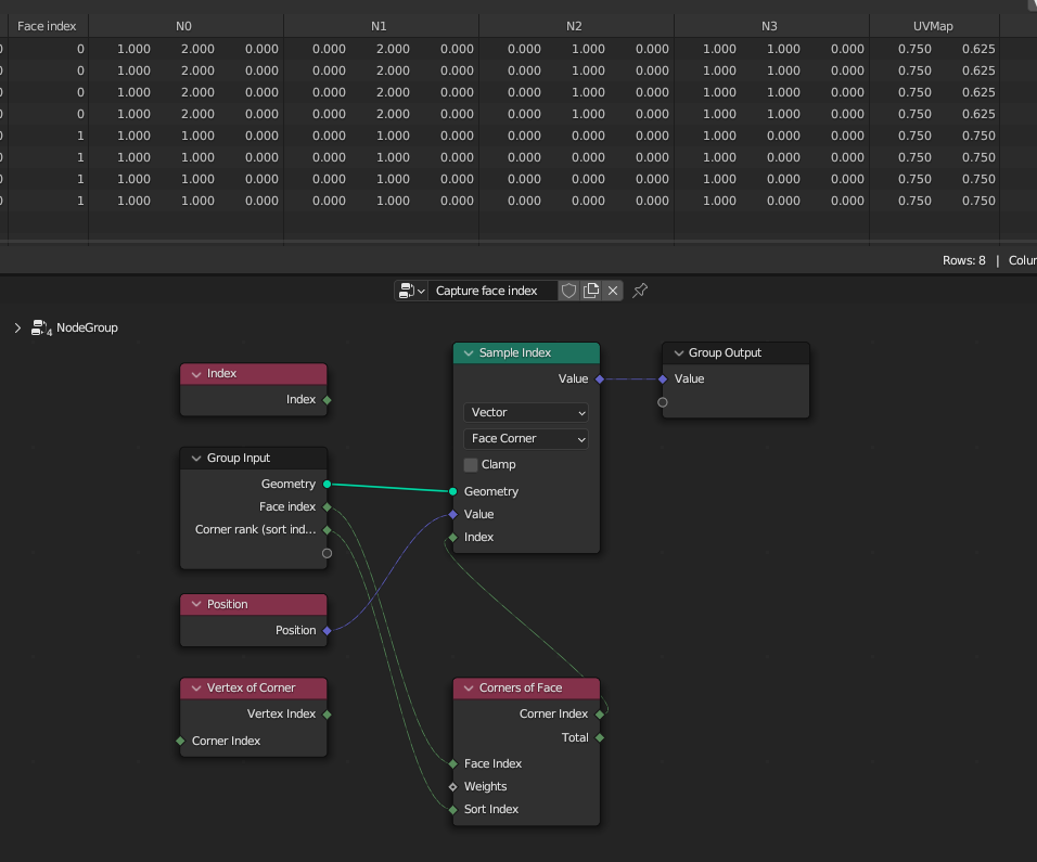
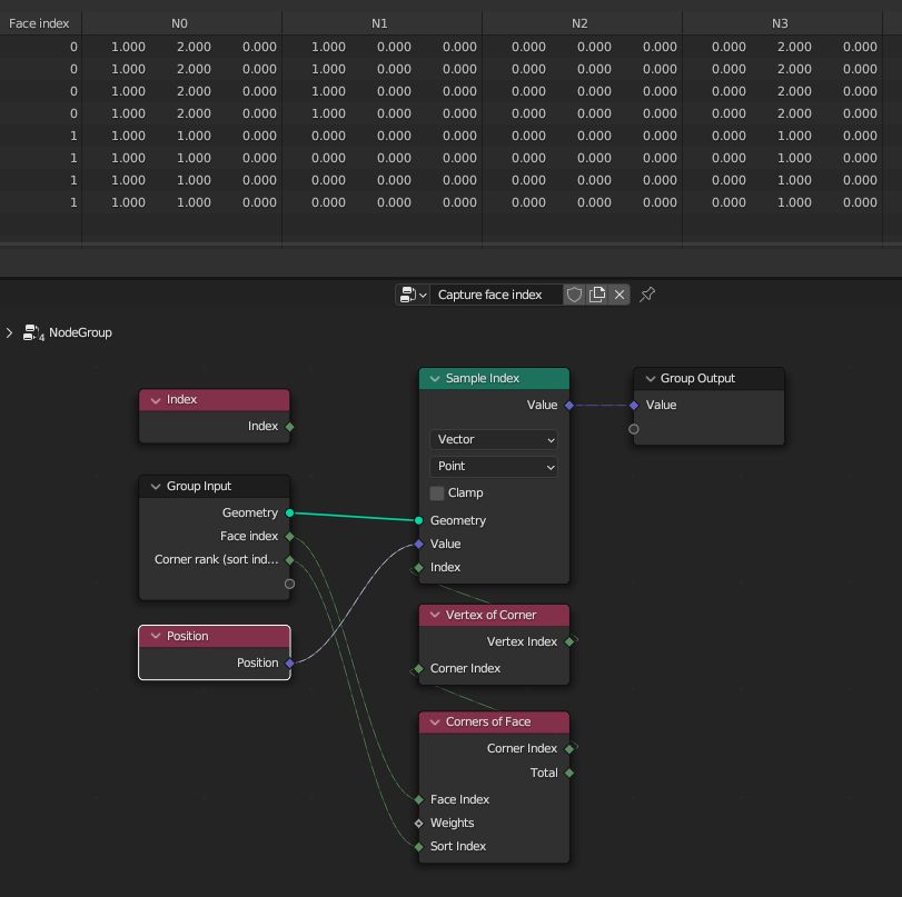
Finally, your 2nd Store Named Attribute (and the logic repeats 3 more times later):
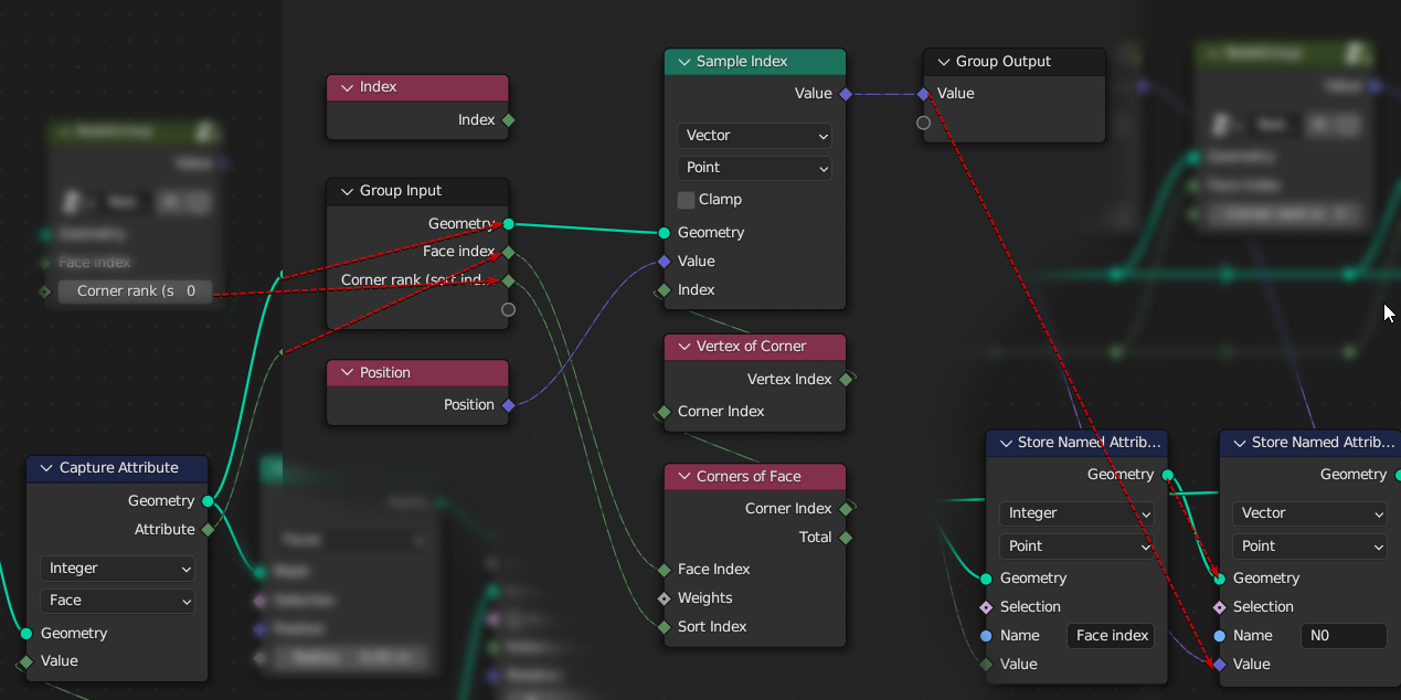
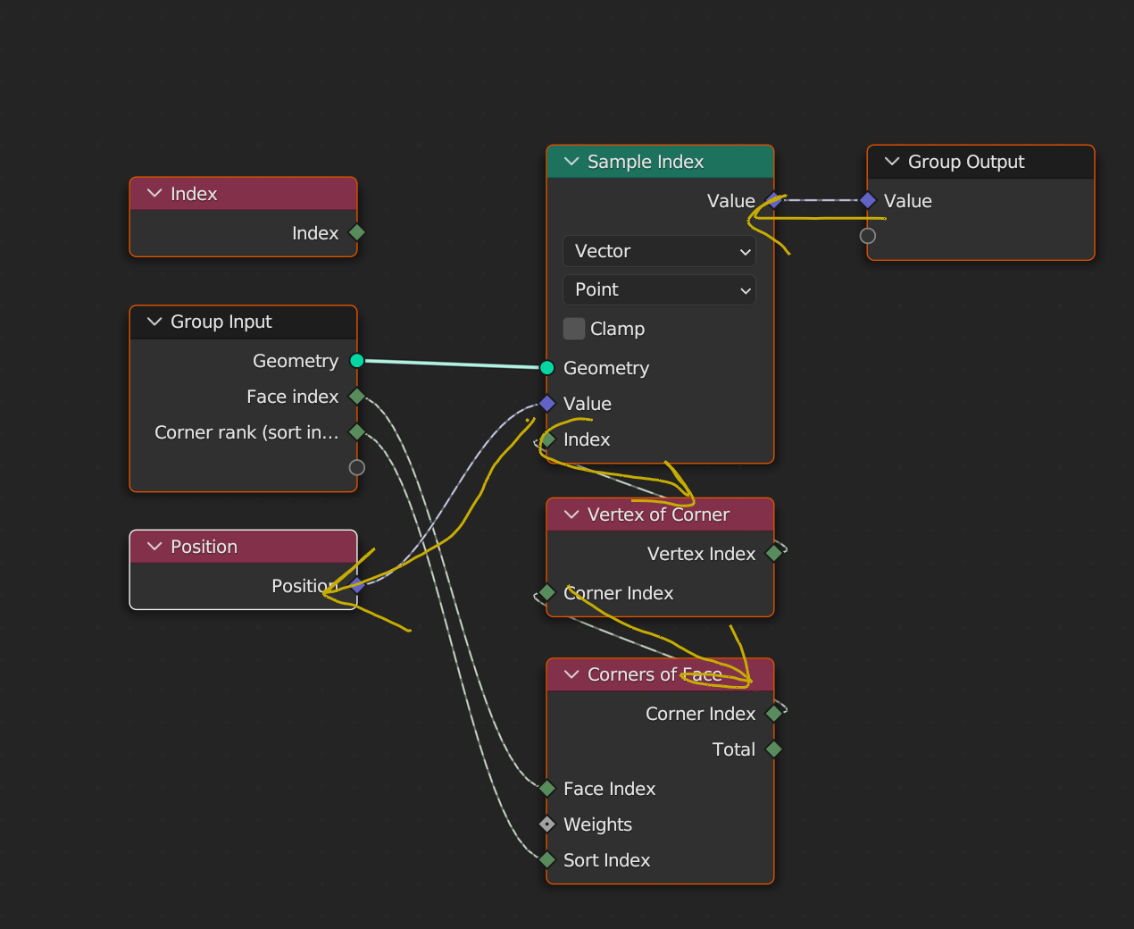
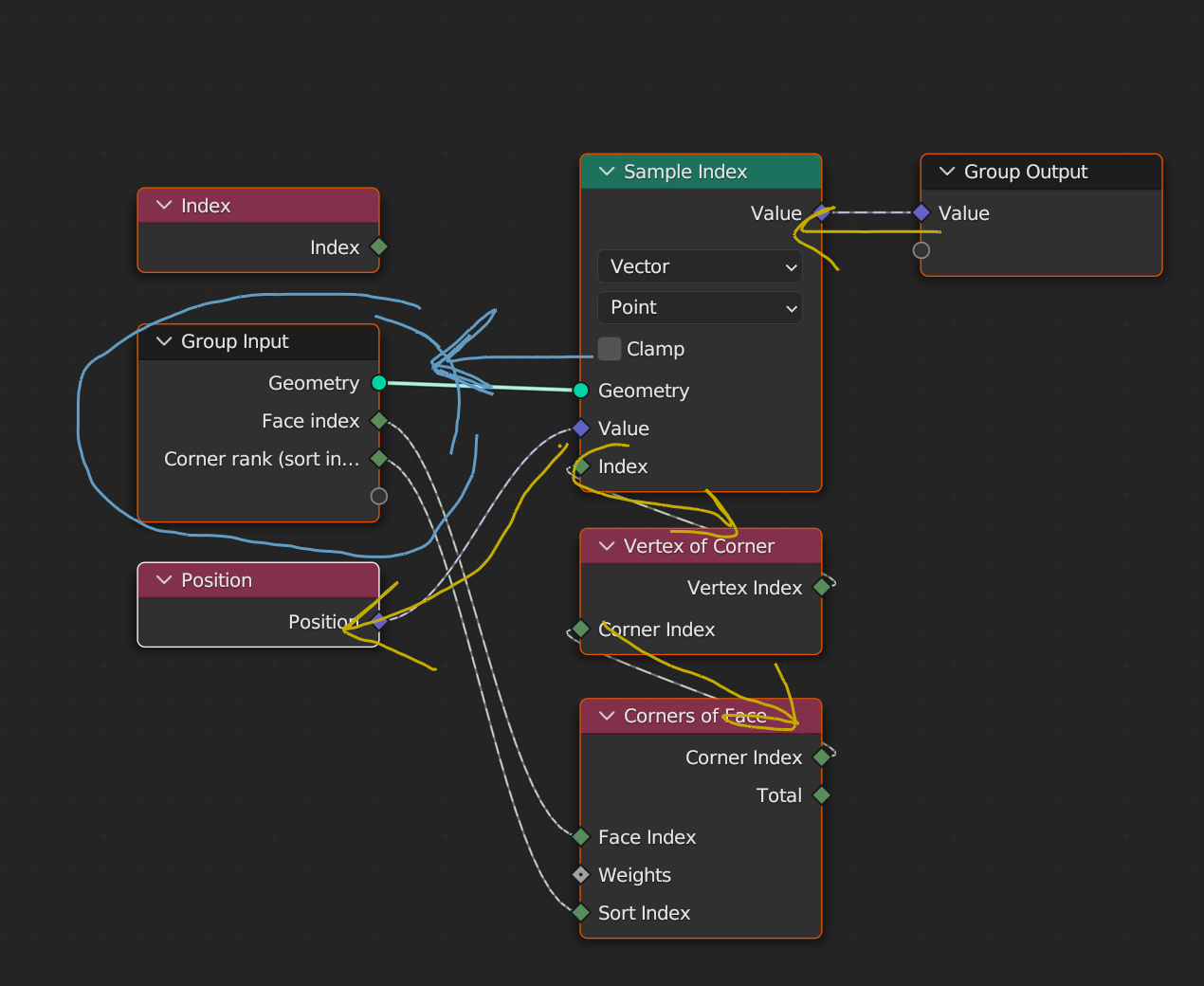
Hopefully my collage is readable:
- Iterate over each point.
- Context is vert#0 from the geometry described most recently in this post.
- Let's follow the arrow in reverse, going to the Group Output, then to Sample Index.
- Sample Index evaluates "Index" field. The context DOESN'T yet change!
- Again we follow backwards to the "Vertex of Corner"
- "Vertex of Corner" needs to evaluate "Corner Index". So again, need to go backwards to "Corners of Face".
- "Corners of Face" needs to evaluate "Face Index" field, so again go backwards to Group Input…
- Group Input got this field from "Capture Attribute" node, so that's the anonymous attribute we stored in the beginning. But remember: the context DIDN'T yet change! We're still evaluate the new goemetry, we're still on vert#0!
- So let me copy-paste the table from which we read:
Vertices_anon_attr: [0, 0, 0, 0, 1, 1, 1, 1]
- We're on first vertex, so we read the first value,
0. Now we can go forward on the field, until we reach "Corners of Face" that requested it.
- "Corners of Face" now reads "Sort Index" which actually is a constant, for the entire tree evaluation it's just
0.
- So "Corners of Face" sorts corners of face#0 by default weights, which I'm 95% sure is index field:
corner#0, corner#1, corner#2, corner#3
- Now it takes the first (index 0) element of this list - corner#0 and finally outputs its index 0 to "Vertex of Corner"
- "Vertex of Corner" checks which vertex is associated with corner#0, let me copy-paste the relevant table from above:
Faces: [(0, 2, 3, 1), (4, 6, 7, 5)]
- So "Vertex of Corner" outputs
0.
- "Sample Index" finally got the index. So now it finally CHANGES context to point (vertex in this case) #0 in the geometry in the output socket of the "Capture Attribute" node. It wants to sample the position. Let me copy-paste the relevant array:
Vertices: [(1,2), (0,2), (1,0), (0,0), (1,1), (0,1)]
- The node is sampling the first element from this array, so position (1, 2). The context returns to vert#0 of the geometry the "Store Named Attribute" operates on currently, and outputs it to the Group Output.
- Group Output sends it further to the "Store Named Attribute"
- The position (1,2) is saved for the first element for
N0 array.
- "Store Named Attribute" increments context to the vert#1 of its left socket geometry and the process continues until all vertices are processed. Then the process is also repeated for next SNA nodes.
Let's analyze the first vertex of N1 node, to confirm the order of sorted face corners:
2'. vert#1
9. Vertices_anon_attr: [0, 0, 0, 0, 1, 1, 1, 1]
10. First Vert again, the value in the anon_attr is 0 again.
11'. In this custom group, the "Corner rank" constant is 1.
12. corner#0, corner#1, corner#2, corner#3
13'. Take the second (index 1) element of this list.
14. Faces: [(0, 2, 3, 1), (4, 6, 7, 5)]
15'. "Vertex of Corner" outputs 2.
16'. Context chnages to vert#2 in the CA out geo.
Vertices: [(1,2), (0,2), (1,0), (0,0), (1,1), (0,1)]
17'. Third element (index 2) is position (1, 0).
The only thing I can add here, is that since "Corner rank" inputs are constants, For each face you will always sample the same corner, therefore 4 first values of each named attribute will always be the same, as well as 4 last values, because you're sampling the same corner, just either from the first or the second face.
More reading:

