2
$\begingroup$

In reality I would like to create dimensions on objects and output the image in Panorama to read in a 360 reading engine.

So I am thinking if it is possible to convert the dimensions into text it would be possible, I had tried to create a script for this, but I encountered problems when the dimension comes it is attached to the world center of Blender.

enter image description here

New contributor
Bolariwan Aurèle LANIGNAN is a new contributor to this site. Take care in asking for clarification, commenting, and answering. Check out our Code of Conduct.
$\endgroup$
1
  • $\begingroup$ What image? What panorama? What is 360 reading engine? $\endgroup$ Commented yesterday

2 Answers 2

3
$\begingroup$

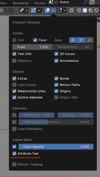
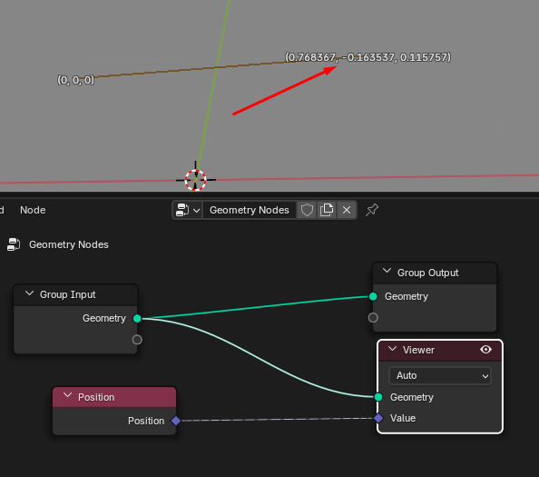
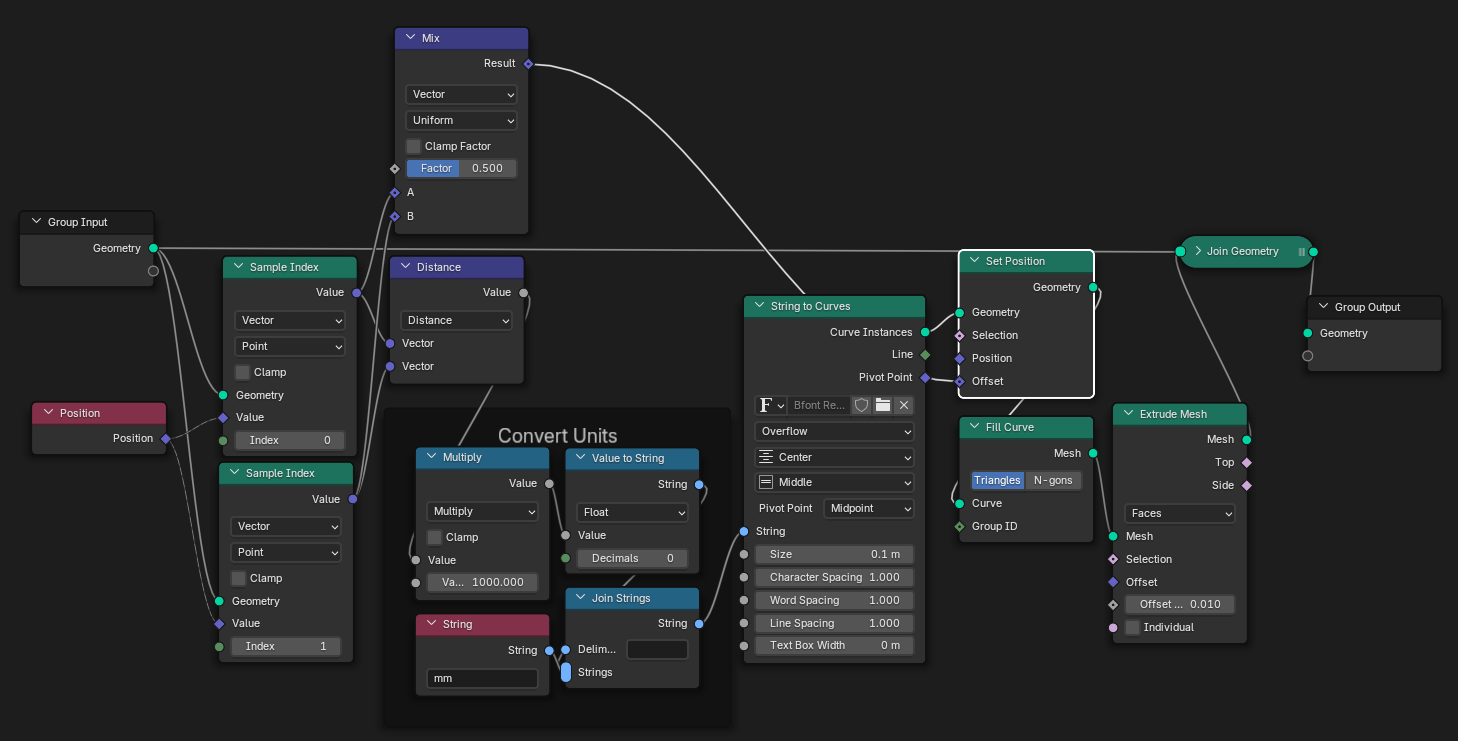
You could make a mesh that consists of a single edge(or whatever else that has something with any coordinates and you can move that - could be two verts, could be single vert and object's origin - whatever). We have the coordinates in Geometry Nodes. You can see them if you enable Viewer Node's Attribute Text overlay:

enter image description here

enter image description here

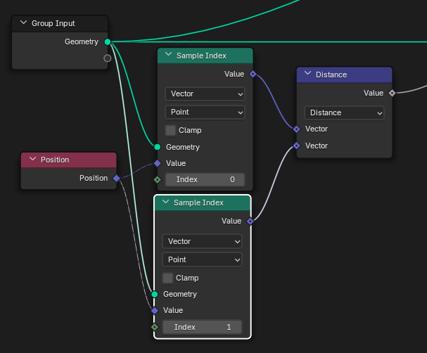
So we have coordinates of vertex one and vertex two. Or as one would say in Nerd: that's vertex 0 and vertex 1. So one can sample the position of those verts with index 0 and 1 and Vector Math node even has Distance mode so there is no need to do any math at all - how good is that?..

enter image description here

All that's left to do is to convert that into text and place it somewhere:

enter image description here

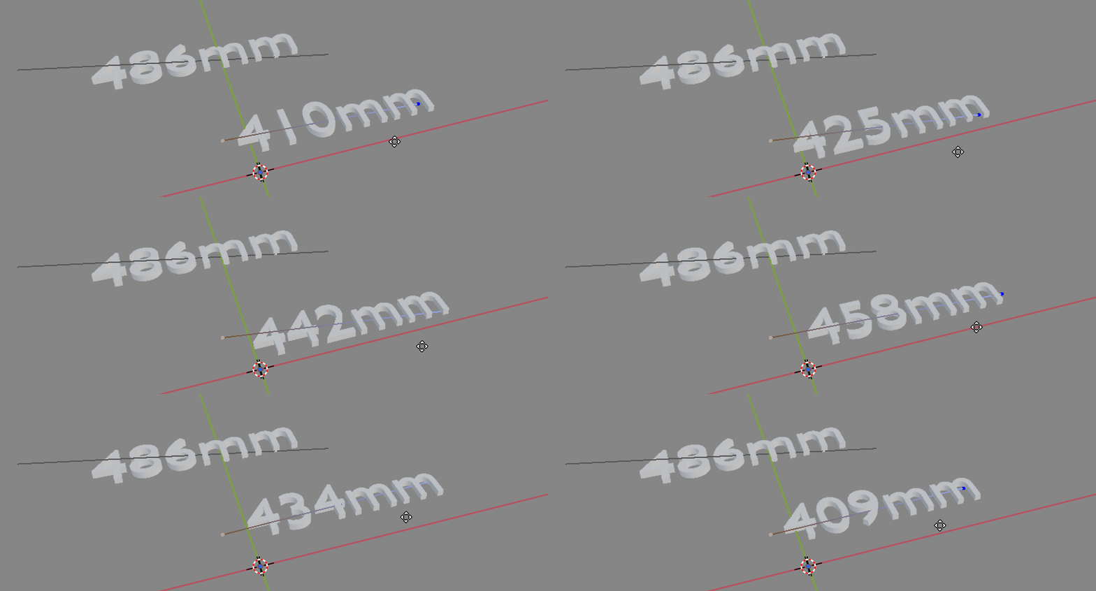
And that's how you have a measurement apparatus constructed with geometry nodes. You can duplicate it easily and snap vertices anywhere.

enter image description here

You can of course place the text anywhere you want and make whatever additional geometry that may help indicate what is measured. You don't need to use the geometry of the object the modifier is on, you could sample another object with the use of Object Info node as well. The possibilities are pretty much endless.

$\endgroup$
4
  • $\begingroup$ waooh amazing, thank. but is not totaly solve my request. I share my script, can you please cket it for me ? $\endgroup$ Commented 18 hours ago
  • $\begingroup$ You got two answers as far. Why didn't they work for you? $\endgroup$ Commented 16 hours ago
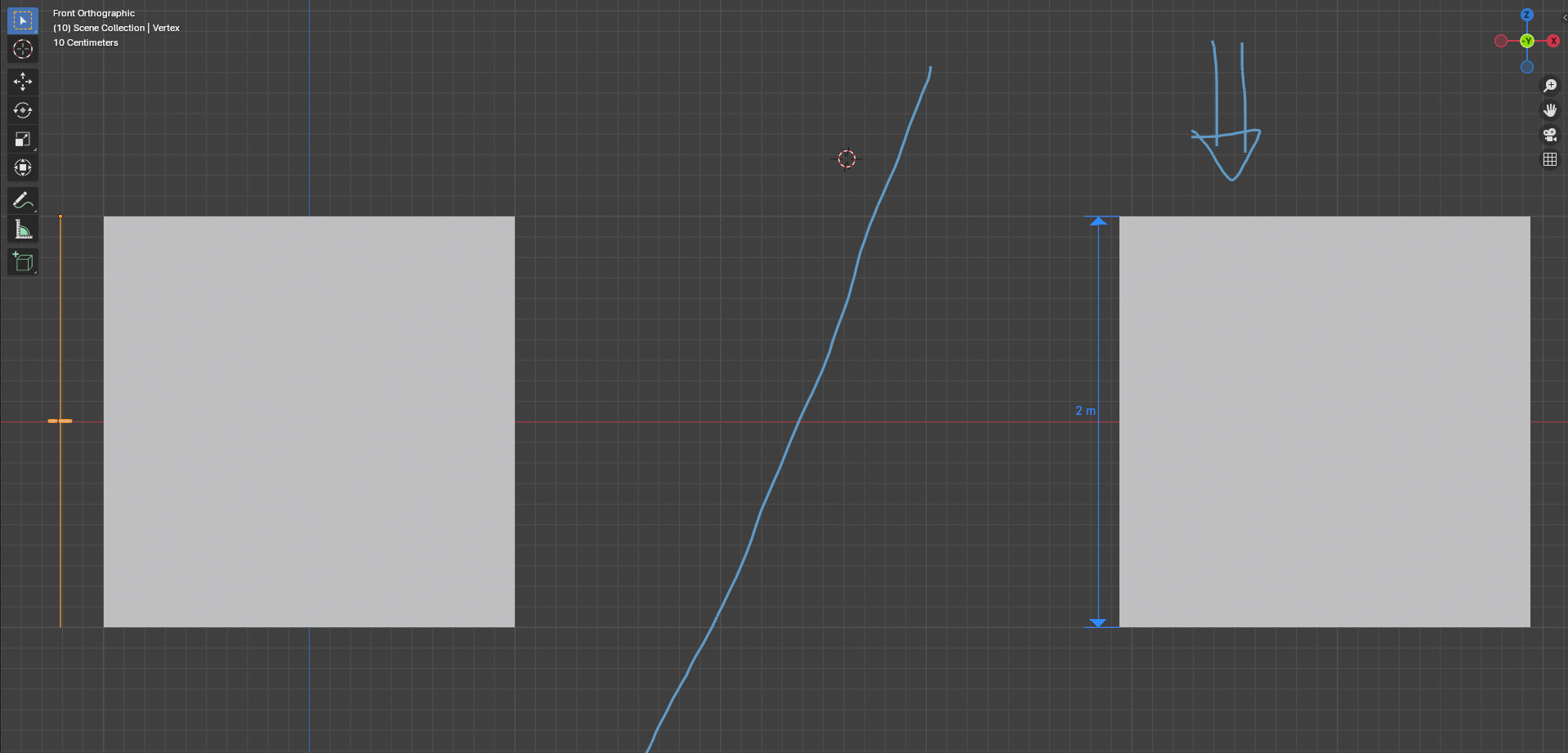
  • $\begingroup$ how to explain it? for example your method is very practical, but it does not allow me for example to have the possibility of rotating the text without really moving the line to which it is attached. I would actually like to have the possibility of putting the text according to the angle of view that I take in order to read the dimension, so if there was a node that I can add to have this option it would be good. also I would like to have at the ends of the dimension line arrows at both ends. and also if possible, a way to dimension the angles $\endgroup$ Commented 15 hours ago
  • $\begingroup$ "but it does not allow me for example to have the possibility of rotating the text without really moving the line to which it is attached" - It absolutely lets you do that and whatever else you may want or imagine! I just don't know what you want to do so I provided a simple example. Maybe add a specific example(an image or a sketch) of the result you want in your question so it's possible to provide more specific answers. $\endgroup$ Commented 14 hours ago
0
$\begingroup$

This script, from Blender Artists worked when I ran it but it has its limitations.

import bpy
from mathutils import *


with open("C:/Users/...YOUR PATH/Desktop/measureit_output.txt", mode="w") as f:

    objects = bpy.data.objects.items()

    for obj in objects:
        mg = obj[1].get('MeasureGenerator')
        if mg:
            obj_name = obj[0]
            for e in mg[0].items():
                if e[0] == 'measureit_segments':
                    ms = e[1]
                    for m in ms:
                        measure_name = m.get('gltxt')
                        measure_points = (m.get('glpointa'), m.get('glpointb'))
                         
                        vdata = obj[1].data.vertices
                        a = vdata[measure_points[0]].co
                        b = vdata[measure_points[1]].co
                        length = (a - b).length
                        print(f"{obj_name};{measure_name};{length:.2f}")
                        f.write(f"{obj_name};{measure_name};{length:.2f}\n")
            print()

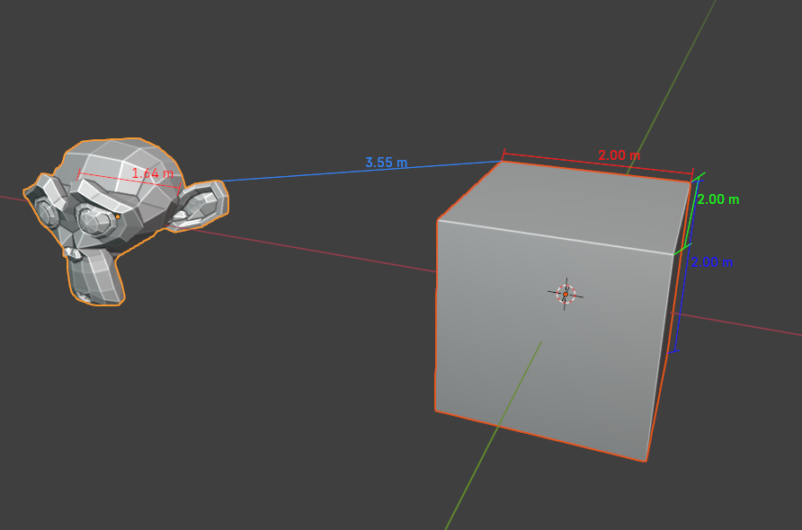
Limitations As I said it has limitations which I can't adequately bug test. It seems to work fine for measurements inside objects, but does not output the distances between between objects or the objects and the origin correctly when I use 'Link' or 'Origin'.

The output.txt file looked like this, notice the last figure is incorrect and does not match with my image:

Cube;Ymeasure;2.00

Cube;Zmeasure;2.00

Cube;Xmeasure;2.00

Suzanne;Xmeasure;1.64

Suzanne;Suzanne-Cube;1.39

A workaround might be creating an object for your measurement such as a simple mesh line.
enter image description here

$\endgroup$
1
  • 1
    $\begingroup$ Perhaps this was part of your approach already. It may help to show people what you have already tried (python, .blend) in order to save time and get a better result. $\endgroup$ Commented 23 hours ago

You must log in to answer this question.

Not the answer you're looking for? Browse other questions tagged .