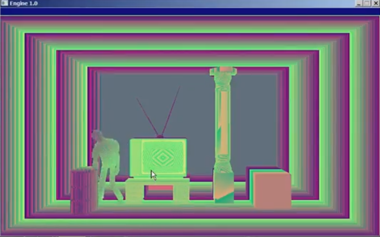
I'm trying to render a RGBA depth map of my scene where each channel byte is a byte of the 32-bit single float Z/depth value. The result will look like a blueish/magentaish render instead of a traditional grayscale black/white image.
I've done this before in C++ in my custom software renderer it's really easy in software you just read the bytes off of the float directly:
i32 IntDepth = *(i32 *)&Z;
byte dR = IntDepth >> 0;
byte dG = IntDepth >> 8;
byte dB = IntDepth >> 16;
byte dA = IntDepth >> 24;
i32 Color = RGBAi(dR, dG, dB, dA);
RenderPixel(Context, X, Y, Color);
I'm completely new to blender's node programming. I'm trying to create a node that does the above. Takes a depth/float as input, and outputs 4 bytes/integers.
Here's what I have so far (modified from this source)
    #NOTE: Run this code first then use SHIFT-A, below, to add Custom node type.

import bpy
from bpy.types import NodeTree, Node, NodeSocket

# Implementation of custom nodes from Python
# Derived from the NodeTree base type, similar to Menu, Operator, Panel, etc.
class MyCustomTree(NodeTree):
    bl_idname = 'CustomTreeType'
    bl_label = 'Custom Node Tree'

# Defines a poll function to enable filtering for various node tree types.
class MyCustomTreeNode :
    @classmethod
    def poll(cls, ntree):
        b = False
        # Make your node appear in different node trees by adding their bl_idname type here.
        if ntree.bl_idname == 'ShaderNodeTree': b = True
        return b

# Derived from the Node base type.
class MyCustomNode(Node, MyCustomTreeNode):
    '''A custom node'''
    bl_idname = 'CustomNodeType'
    bl_label = 'DepthToRGBA'
    bl_icon = 'INFO'

    def update_value(self, context):
        self.outputs["Depth"].default_value = self.Depth
        Bytes = bytearray(struct.pack("f", self.Depth))
        self.R = Bytes[0]
        self.G = Bytes[1]
        self.B = Bytes[2]
        self.A = Bytes[3]
        self.outputs["R"].default_value = self.R
        self.outputs["G"].default_value = self.G
        self.outputs["B"].default_value = self.B
        self.outputs["A"].default_value = self.A
        self.update ()

    R = bpy.props.IntProperty(update = update_value)
    G = bpy.props.IntProperty(update = update_value)
    B = bpy.props.IntProperty(update = update_value)
    A = bpy.props.IntProperty(update = update_value)
    Depth = bpy.props.FloatProperty(update = update_value)

    def init(self, context):
        self.outputs.new('NodeSocketInt', "R")
        self.outputs["R"].default_value = self.R
        self.outputs.new('NodeSocketInt', "G")
        self.outputs["G"].default_value = self.G
        self.outputs.new('NodeSocketInt', "B")
        self.outputs["B"].default_value = self.B
        self.outputs.new('NodeSocketInt', "A")
        self.outputs["A"].default_value = self.A
        self.inputs.new('NodeSocketFloat', "Depth")
        self.inputs["Depth"].default_value = self.Depth

    def update_output(self, out_name):
        #Review linked outputs.
        try:
            out = self.outputs[out_name]
            can_continue = True
        except:
            can_continue = False
        if can_continue:
            if out.is_linked:
                # I am an ouput node that is linked, try to update my link.
                for o in out.links:
                    if o.is_valid:
                        o.to_socket.node.inputs[o.to_socket.name].default_value = self.outputs[out_name].default_value

    def update(self):
        self.update_output("R")
        self.update_output("G")
        self.update_output("B")
        self.update_output("A")
        print(self.outputs["R"])
        print(self.outputs["G"])
        print(self.outputs["B"])
        print(self.outputs["A"])


    # Optional: custom label
    # Explicit user label overrides this, but here we can define a label dynamically.
    def draw_label(self):
        return "DepthToRGBA"

### Node Categories ###
import nodeitems_utils
from nodeitems_utils import NodeCategory, NodeItem

# our own base class with an appropriate poll function,
# so the categories only show up in our target tree type
class MyNodeCategory(NodeCategory):
    @classmethod
    def poll(cls, context):
        b = False
        # Make your node appear in different node trees by adding their bl_idname type here.
        if context.space_data.tree_type == 'CompositorNodeTree': b = True
        return b

# all categories in a list
node_categories = [
    # identifier, label, items list
    MyNodeCategory("SOMENODES", "Saedo Nodes", items=[
        NodeItem("CustomNodeType"),
        ]),
    ]

def register():
    bpy.utils.register_class(MyCustomNode)
    nodeitems_utils.register_node_categories("CUSTOM_NODES", node_categories)

def unregister():
    nodeitems_utils.unregister_node_categories("CUSTOM_NODES")
    bpy.utils.unregister_class(MyCustomNode)

if __name__ == "__main__":
    register()
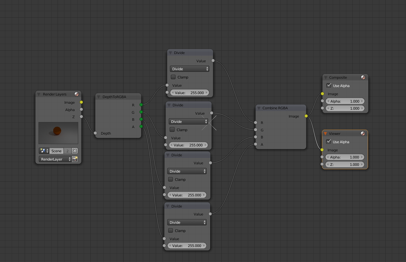
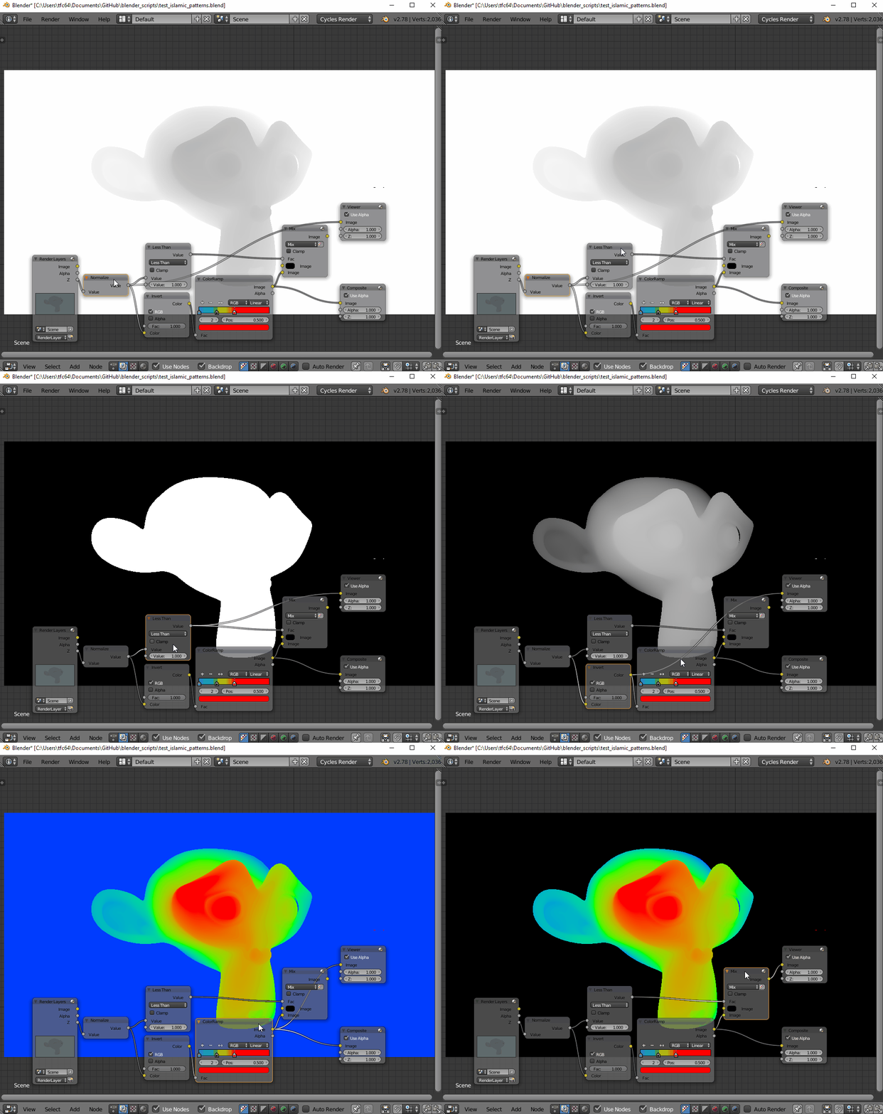
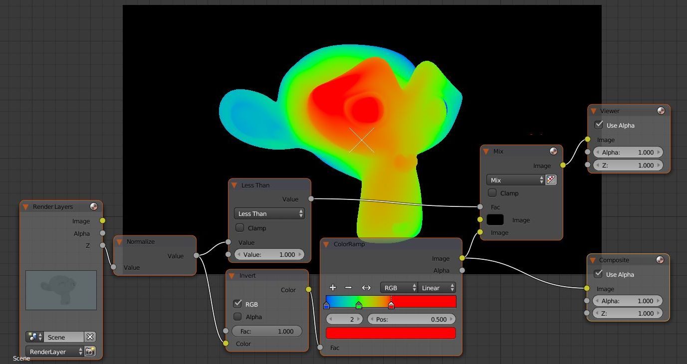
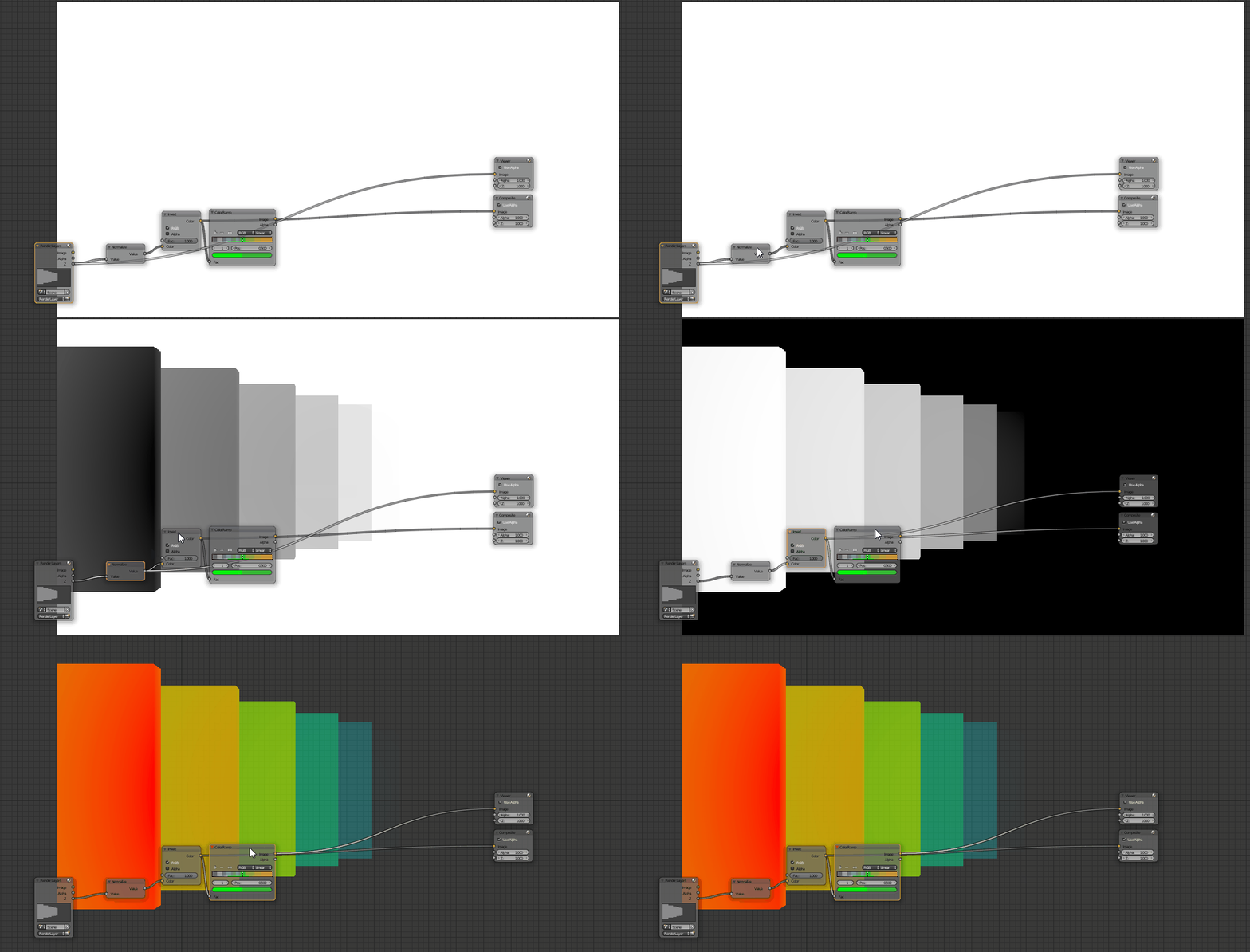
I'm not sure what I'm doing wrong but it doesn't seem to be working, "Backdrop" is ticked but nothing shows up. Here's my node setup in blender:
I figured I need those divides by 255 since bytearray returns values in the range [0->255], is that correct?
My questions:
- How can I just debug the values returned by bytearray? I have a
couple of
prints there but they don't see to be getting called at all. - Every time I run script, then modify something in it, I can't run it again unless i close/restart blender. It says Category "CUSTOM_NODES" is already registered. Is there a way around that?
- Finally, how do I correctly get the affect that I want? is struct.pack the right way to do it in python or?
EDIT: Old engine video, but this is what I want to achieve. @1:55 https://www.youtube.com/watch?v=ouYT_MBPB84
EDIT: More details based on conversation with the super helpful TLousky
First I really appreciate your help! As I was trying to read the texture in engine, I was thinking about it I don't think this RGB mapping gives me the effect I want.
Here's the rundown: We're making a game with prerendered backgrounds, similar to the old FF and Resident Evil games. The artist gives me a colormap of the rendered scene, a lowpoly mesh for collision and a depth map/image corresponding to that render. The depth map is used to create the illusion of depth/occlusion so if something's in front of the player, it would render on top.
The way we do that is: 1) First fill the color buffer with the background 2) Fill the depth buffer with the depth map 3) Render 3D objects normally. Since the depth buffer is already populated, things get occluded correctly. Assuming of course the engine uses the same camera and near/far plane settings as used in the actual render.
The traditional way of doing depth maps is just a grayscale image, where R=G=B=A = depth*255, depth is normalized in the range [0, 1]. The problem with this is we're compressing a float which is 4 bytes, to a single byte. Going down from a huge range to a much smaller one. So when the engine tries to read the depth map, it will get much less accurate results, there's no way it would get the real depth that was encoded this way.
Example:
- Writing:
- depth = 0.755313
- R=G=B=A = (byte)(depth*255.0) = (byte)(192.604815) = 192
- Reading: (pick any channel)
- depth = R/255.0 = 192/255.0 = 0.752941
Not the same number! This was just an example there could be more accuracy lost.
So I thought why not take each of the float's bytes and broadcast them to each channel. So now R=Byte0, G=Byte1, B=Byte2, A=Byte3. Nothing's lost at all! When reading the depth map now, I can read the values of R/G/B/A, do some bit-shifting and bitwise-OR and get the exact depth that was encoded.
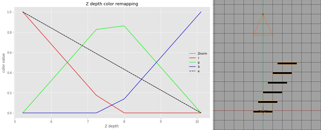
The depth image this way would result in each pixel having color contributions from each channel, instead of red being the closest, blue being the farthest. Something like the following:
(Note: for this shot, the prerendered background and depth image were generated from the engine itself as a test so I had total control, and not from Blender otherwise I wouldn't be asking)

