4
$\begingroup$

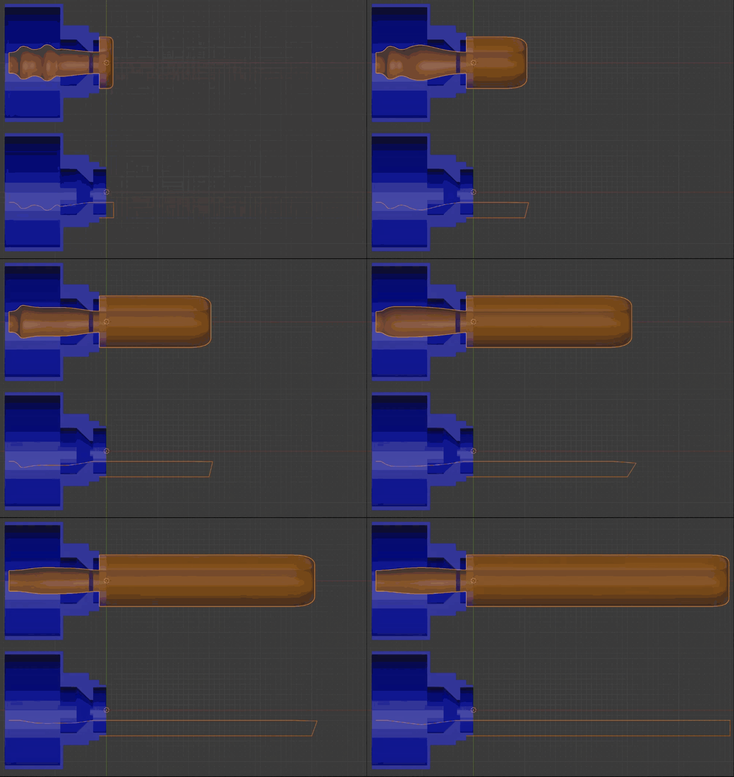
I am a beginner in Blender. For a research project, I am creating an animation to unravel a tube from the inside out. Using this post as a guide, I have created a line of vertices, curled it up, added a subdivision modifier, and then a screw modifier to revolve the created profile around itself (The suggested cast modifier seemed to have no effect, so I removed it.).

To animate the unraveling/ growing from the inside out, I have manually moved each vertex through a series of keyframes using AnimAll. The image below shows the direction of travel of the vertices between keyframes (indicated by the arrows). See the gif below for the resulting animation.

Since I have to individually move each vertex for each keyframe, it is difficult to dynamically change the animation. Is there a better way to animate the growth of the tube to any desired length? To show the mechanism of movement, the material needs to originate from inside the blue object and move through the inside of itself before being deposited at the tip.

Additionally, I want the tube to follow a specified path rather than just growing in a straight line. How could that be done?

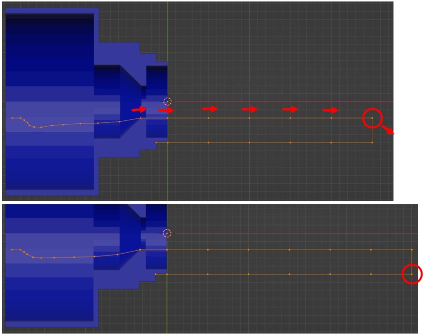
How vertices are moved between keyframes

Example of inverting tube

$\endgroup$
4
  • $\begingroup$ What to you expect in termes of animation concerning the left part? $\endgroup$
    – lemon
    Commented Jan 30 at 15:51
  • $\begingroup$ @lemon The tube is supposed to be bunched up inside the blue object. The blue object itself does not require animation. However, if I cannot animate that, I am fine with just making any part of the tube extending too far to the left invisible. $\endgroup$
    – Custos
    Commented Jan 31 at 8:53
  • $\begingroup$ ok, I had this so far i.sstatic.net/S43jv.gif . But if you can hide the left part, that can be simplified a lot (just solidifying a bevelled curve). $\endgroup$
    – lemon
    Commented Jan 31 at 9:25
  • $\begingroup$ @lemon It seems like you used a different approach to Duarte Farrajota Ramos' answer. Can you tell me how you did this so I can learn a bit more and see which approach gives me the best results? $\endgroup$
    – Custos
    Commented Feb 1 at 8:11

2 Answers 2

5
$\begingroup$

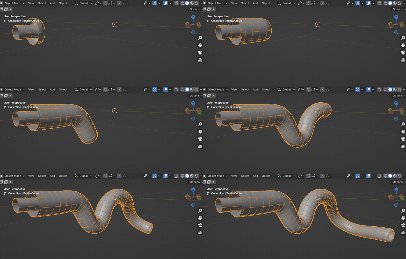
Here a slightly simpler technique. It has its own set of limitations, but uses a Curve modifier and requires less manual labour.

Create a bezier curve roughly following the desired shape for the unwinding hose section. Make sure the curve object origin sits at the end of the outer edge of the hose path.

Create a mesh object with a single short edge and no faces. Adjust its origin so it sits at the axis of revolution of the tube shape. Adjust the position of the vertex so they land at the the beginning of the curve, where it's origin sits at.

Add an array modifier to the mesh, set it to Fit Curve and pick the curve created at the first step. Make sure to turn on Merge to get a continuous string.

Now add a Curve modifier to the mesh, and set it again to the same bezier curve object.

Add a Screw modifier to the mesh, adjust the axis accordingly.

Make sure both the mesh and the bezier curve have to same rotation in world space, otherwise you may get unexpected behaviour.

Move the bezier curve horizontally and you can animate the inflation of the hose tube.

Optionally you can now additionally animate the bezier curve points with shape keys, to get additional deformations and or stretching effects.

$\endgroup$
1
$\begingroup$

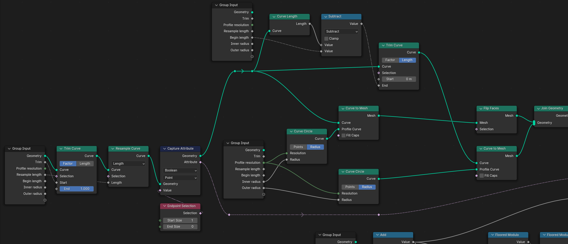
Using geometry nodes,

enter image description here

Define a curve and give it the shape you want. It is the node setting input geometry.

enter image description here

Trim the curve to animate it.

Resample at some length.

Capture the end point (begining of the curve in this setting).

Duplicate it and give at each a profile of the desired size.

Join them.

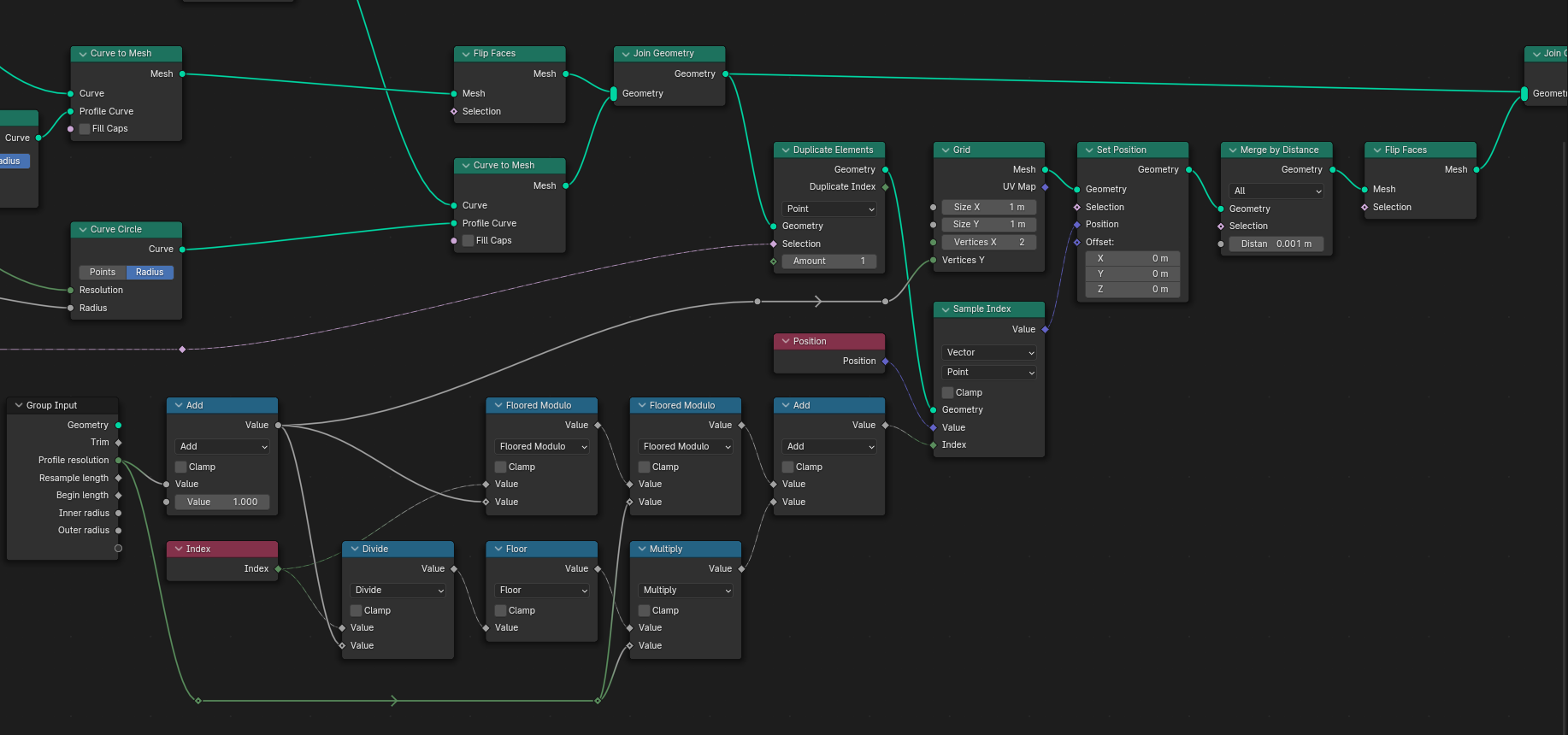
Next we want to fill the extremity:

enter image description here

It uses a grid whom size depends on the profile resolution (2 columns of vertices and resolution + 1 as height, so that we can close it).

Then we take the curves profiles positions at it captured endpoint and give these positions to the grid.

Merge the extremities of this disk.

Join all.

(Blender 4.0)

Note: if the left part of the tube does not matter, you can also simply bevel a curve and solidify it. Then animate its start/end mapping. Which is much more simple.

$\endgroup$

You must log in to answer this question.

Not the answer you're looking for? Browse other questions tagged .