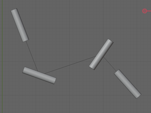
What I want to do is the following: I want some way to easily make objects that look like a system of tubes or pipes. I start with an easily-editable mesh that is basically extruded points (edit mode of a cube, select all vertices, merge at center, extrude extrude extrude and then you end up with a segmented line like in the picture below, the black lines underneath the cylinders). I tried with the solidify modifier and some other ways but they all don't give me the corners I'm looking for, so now I'm trying to implement the following strategy.
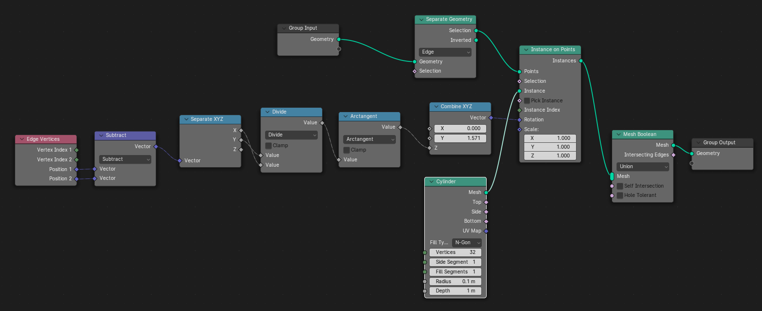
My current approach is: if I make a geometry node that will position a cylinder at each vertex of my mesh except the last one, then orient that cylinder so that it points toward the next vertex in the mesh, and then scale it to the length of the edge, I'll have the connecting pipes part done (I'll then add spheres on each vertex to fix up the corners). I tried several different approaches in geometry nodes. The most promising is also the most straightforward: for each edge, I take the location of the start- and end point; subtract them from each other; then rotate the cylinder around the Z axis by the angle of the result of that subtraction (I'm only doing this in 2D, so we can assume the Z position of all vertices is the same). This should be possible with some simple trig. And indeed it works for the first and last vertex, but not the ones in between. Note in the screenshot below that the first and last cylinders are aligned with the edges connected to them, the others are sort of in the middle between the two edges connected to them (but not exactly). When I move the edges around, the rotation of the cylinders on those two points tends to flip around quite a bit, while those at the ends stay correct. So this doesn't seem like it's an issue with flipping signs because the result of the subtraction is in another quadrant.
This is my node setup:
Any ideas on what I could be looking at? Or even just tricks on debugging geometry nodes? I've found the 'spreadsheet' view but I'm having a really hard time finding out what values are being passed around, and the concept of the 'fields' in- and outputs is making things quite a bit worse. Yes I've watched several Youtube videos (and the manual) on what they are and how they work, but I can't seem to get them to work with the 'instance on points' and related nodes.


